


Flexible PCB design guidelines: start with the application
Flexible PCB design guidelines help OEM teams connect electrical requirements, mechanical movement and manufacturing documentation before a circuit is released for quotation. A layout can fit on a screen yet leave the supplier unsure about the installed shape, connector thickness or acceptance test.
This guide provides a practical review sequence for hardware engineers, mechanical designers and B2B buyers. Start with the application, agree the construction, and issue a consistent revision-controlled RFQ package. Numerical limits and qualification requirements must be agreed for the actual material stack-up and operating conditions.
The most useful starting point for flexible PCB design is a written description of what the circuit must do inside the finished assembly. Identify which sections remain fixed, which are formed during installation, and which move repeatedly during normal use. Include how the product is assembled and serviced, because installation can impose a different bend from operation.
Create a one-page application brief before requesting a detailed quotation. State the electrical function, available routing space, connector locations, operating environment and expected service life. If the circuit connects a display to a controller, specify whether the display is stationary or moves on a hinge. If it crosses a robot joint, describe the motion envelope and where the circuit is supported.
Assign an owner to each requirement
Electrical engineering should own the netlist and signal requirements. Mechanical engineering should own the installed shape and clearances. Quality should define verification and acceptance evidence, while purchasing should own quantity assumptions and commercial comparisons. Record who approves a change that affects more than one discipline.
Teleconix's flexible PCB product categories can help you describe the application when opening a discussion. Treat a catalog example as a starting point for requirements, rather than proof that a different custom design has already been qualified. The immediate deliverable is a shared brief that every shortlisted supplier receives.
Where a requirement is unknown, write “to be agreed” and name its owner. An explicit open question is easier to resolve than a hidden assumption discovered after a purchase order has been placed.
Choose the construction and define the stack-up
Compare single-sided flex, double-sided flex, multilayer flex and rigid-flex against the same application brief. The objective is to select a construction that serves routing, packaging and assembly needs without adding unnecessary complexity. A familiar layer count from an earlier project is not, by itself, a reason to reuse that construction.
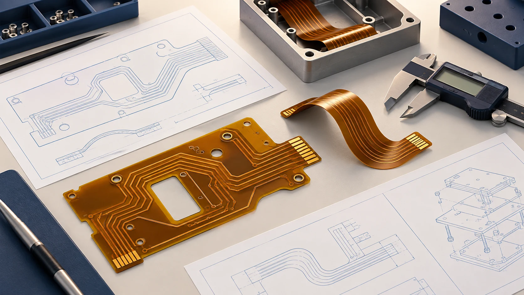
Prepare a flex PCB stack-up drawing that distinguishes the flexible span from locally reinforced or rigid areas. Label the dielectric, copper, coverlay, adhesive and stiffener where applicable. Identify which thicknesses are nominal and which finished dimensions require an agreed tolerance. Avoid a single overall thickness note when different regions perform different mechanical functions.
Make material choices traceable
Material names need more detail than “polyimide.” Ask for the proposed material grade, relevant supplier data sheet and permitted substitution process. Pyralux material information illustrates that flexible-circuit laminates and adhesive systems form a product family; a family name is not a complete purchasing specification.
Record whether an alternative material is acceptable and who must approve it. If a supplier proposes a different construction, request a marked-up stack-up and an explanation of its effects on your critical requirements. Keep the original and proposed versions together so the decision remains understandable later.
For the buyer, the important comparison is whether quotations describe the same deliverable. Confirm the manufacturing scope, including bare-board supply versus component assembly. Do not assume that a quotation for a flexible circuit also includes connectors, stiffener installation, forming, assembly fixtures or final functional testing.
For the material decision behind this construction, use the flexible PCB materials and stack-up selection guide to compare copper, coverlay, adhesives and stiffeners before approving the RFQ.
Define bend conditions before setting layout rules
A flex PCB bend radius requirement should describe the actual installation and motion, not just a number copied into a drawing. Mark the intended bend region, the bend direction and the installed form. For moving applications, also document the range of motion, cycle target and operating conditions that the verification plan must reproduce.
Static installation and repeated movement are different use cases. Avoid applying a universal radius multiplier to every design. Ask the fabricator to review the proposed bend against the full construction, then agree how suitability will be demonstrated. A thicker reinforcement at an endpoint does not describe the thickness of the moving span.
For an application-level comparison, use the static vs dynamic flex PCB bend radius guide to define the motion path, stack-up review and prototype validation inputs.
Review the assembly path
Include the route that installers take when feeding the circuit through an enclosure. Ask whether temporary twisting, pulling or folding is required before the circuit reaches its final position. A convenient final layout may still be difficult to assemble consistently.
Use a drawing or a simple physical mock-up to communicate this path. Mark the support points and show where surrounding parts could touch the flex. If the enclosure or hinge changes, reopen the review instead of assuming the previous assessment still applies.
For applications involving movement, the robotics and industrial FPC category provides relevant application context. Qualification still belongs to the specific circuit and assembly. Keep illustrations, proposed geometry and completed test evidence clearly distinguished in the project record.

Review traces, transitions and connector support
Mechanical features deserve a deliberate review alongside the schematic. Inspect the proposed bend region for pads, vias, abrupt geometry changes and interfaces to supported areas. Ask the manufacturer to identify features that should move or receive additional review before the artwork is frozen.
这 All Flex circuit design guide discusses conductor geometry, coverlays, shielding and stiffeners as connected design topics. Its published supplier-specific dimensions should not be copied into a Teleconix drawing without agreement. Use such references to frame questions, then resolve those questions against the selected process and construction.
Check the complete mating interface
For a connector interface, include the connector manufacturer's drawing and part number in the review package. Confirm contact orientation, insertion direction and the finished mating thickness. Record the relevant dimensional tolerances rather than relying on an image of the connector.
A stiffener is a local mechanical feature, so its outline, location and material need to be visible in the documentation. Ask who checks its placement relative to the connector and intended bend region. When dimensions are critical, define the measurement method as well as the acceptance limit.
For a display connection, compare the circuit drawing with the module and enclosure drawings together. Teleconix's display FPC applications provide a relevant starting point for the discussion. Resolve the actual module interface before selecting a catalog example as a reference.
Document electrical and assembly acceptance criteria
A complete flex PCB DFM checklist includes what must be verified, who verifies it and what evidence is delivered. Separate fabrication checks from assembled-product tests. Passing a bare-board electrical test does not, by itself, demonstrate that the circuit works in the customer's complete system.
List the critical electrical requirements in a controlled document. If the design needs controlled impedance, identify the relevant nets, target, tolerance and agreed verification approach. Ask how the proposed stack-up and the test evidence will be linked. Avoid leaving a general “high-speed” note as the only instruction.
Agree the test boundary
For an assembled flex circuit, define which party supplies components, programming data, fixtures and test procedures. Clarify whether the quotation covers component placement only or a broader assembly and inspection scope. Request confirmation for each service instead of inferring it from the word “turnkey.”
State how nonconforming parts will be identified and how deviations are approved. For prototypes, an engineering concession may be appropriate, but it should be documented and should not silently become the production specification.
Prepare an acceptance matrix with one row per critical characteristic, its drawing reference, responsible party and required evidence. Mark requirements that still need an engineering decision. The matrix becomes a useful agenda for the supplier review and prevents procurement from accepting a quote while key quality expectations remain unresolved.
If a regulated end application requires particular certification or traceability, request the applicable evidence and scope directly. A reference to an industry on a website is not a substitute for project-specific approval.
Build a revision-controlled RFQ package
Consistent input files make FPC design and manufacturing discussions more productive. Issue one named release package rather than distributing separate attachments across several email chains. Give each document a revision and identify the authoritative drawing if other files are supplied for reference.
| Package item | What to include | Review owner |
|---|---|---|
| Fabrication data | Agreed artwork format, drill data, outline and units | Electrical engineering |
| Mechanical definition | Installed shape, bend regions, supports and mating interfaces | Mechanical engineering |
| Construction | Stack-up, materials, finishes and stiffener details | Engineering and supplier |
| Assembly scope | BOM, placement information and test requirements when applicable | Manufacturing engineering |
| Acceptance criteria | Critical dimensions, required inspections and evidence | 质量 |
| Commercial brief | Prototype quantity, production forecast and delivery destination | Purchasing |
Before sending the package, check that the outline and revision agree across the files. List intentionally missing information, such as an unresolved material alternative, in a question log. Ask the supplier to quote against the named release and identify assumptions explicitly.
Use the Teleconix custom FPC project page to frame the discussion, then confirm file-transfer arrangements and the exact supply scope with your contact. Share only information needed for the review under your organization's engineering-data procedures.
When a design changes during quotation, send a complete replacement release with a short change summary. State whether the previous quotation needs to be revised. This reduces uncertainty over whether engineering and purchasing are discussing the same circuit.
Compare quotations and plan prototype approval
The lowest unit price is difficult to interpret when quotations use different assumptions. Compare tooling, test fixtures, documentation, packaging and delivery terms alongside the circuit price. Separate one-time charges from recurring charges so prototype and production economics remain understandable.
Ask each supplier to identify exclusions and unresolved technical questions. A quotation may be conditional on a layout change, material availability or a different inspection scope. Move those conditions into the project decision log before awarding the order.
Define what the prototype must answer
A prototype build should have a written purpose. Decide whether it evaluates fit, electrical behavior, assembly handling or a defined reliability requirement. A successful fit check is useful evidence for fit; it is not automatically evidence for every other requirement.
Record the approved drawing revision, build configuration and any deviations with the evaluation results. When possible, use the intended enclosure and mating components rather than judging the circuit in isolation. Identify differences between the prototype setup and the planned production setup.
Close the review with three clear decisions: what has passed, what remains open and who can authorize production release. If a change affects a critical requirement, agree which checks must be repeated. Avoid describing an early sample as “production approved” while open actions remain.
This is also the right time to discuss realistic order quantities and replenishment needs. Request project-specific lead-time and minimum-order information; do not assume a general website statement is a commitment for your custom construction.
Example: resolving two different quotations
Consider an illustrative OEM project in which one quotation covers bare circuits and another includes local reinforcement and additional documentation. The buyer should first reconcile the scope, not negotiate the price difference immediately. Put the deliverables into a comparison sheet and ask each supplier to confirm the same baseline.
Next, review any proposed material alternatives with engineering. Record whether the alternative is accepted for the prototype only or for future production as well. If the project requires a customer approval before substitution, make that approval a visible release condition.
Finally, compare the revised quotations and retain the answers with the purchase order. This example is a purchasing workflow, not a Teleconix customer case or a cost-saving claim. Its purpose is to show how a transparent comparison turns an apparently simple price decision into a review of the actual product and evidence being purchased.
Use one final DFM review before release
Bring engineering, quality and purchasing together for a short release review using the same package. The aim is to close decisions, not simply collect signatures. Ask each owner to show the evidence for the requirements they approve.
- Application: Is the installed form and expected motion documented?
- Construction: Is the proposed stack-up approved and revision controlled?
- Interfaces: Are connector drawings, contact orientation and local support defined?
- Layout: Have the supplier's DFM questions been answered in the released files?
- Verification: Are tests, sample requirements and acceptance evidence agreed?
- Commercial scope: Does the purchase order match the quotation's assumptions?
- Change control: Is there a named approver for substitutions and deviations?
For every open action, record an owner and a due date. An action can remain open during early feasibility work, but the team should understand what it prevents: a firm quotation, prototype manufacture or production approval. This keeps schedule discussions grounded in actual decisions.
Keep the approved package, supplier responses and prototype findings together. They form the baseline for the next build and make future changes easier to review. When another engineer or buyer joins the project, the record should explain both the selected construction and why it was accepted.
The following application examples are navigation aids for discussing a project with Teleconix. Confirm the proposed specification and supporting evidence for your own design rather than treating an example product or solution as automatic qualification.
Related Products
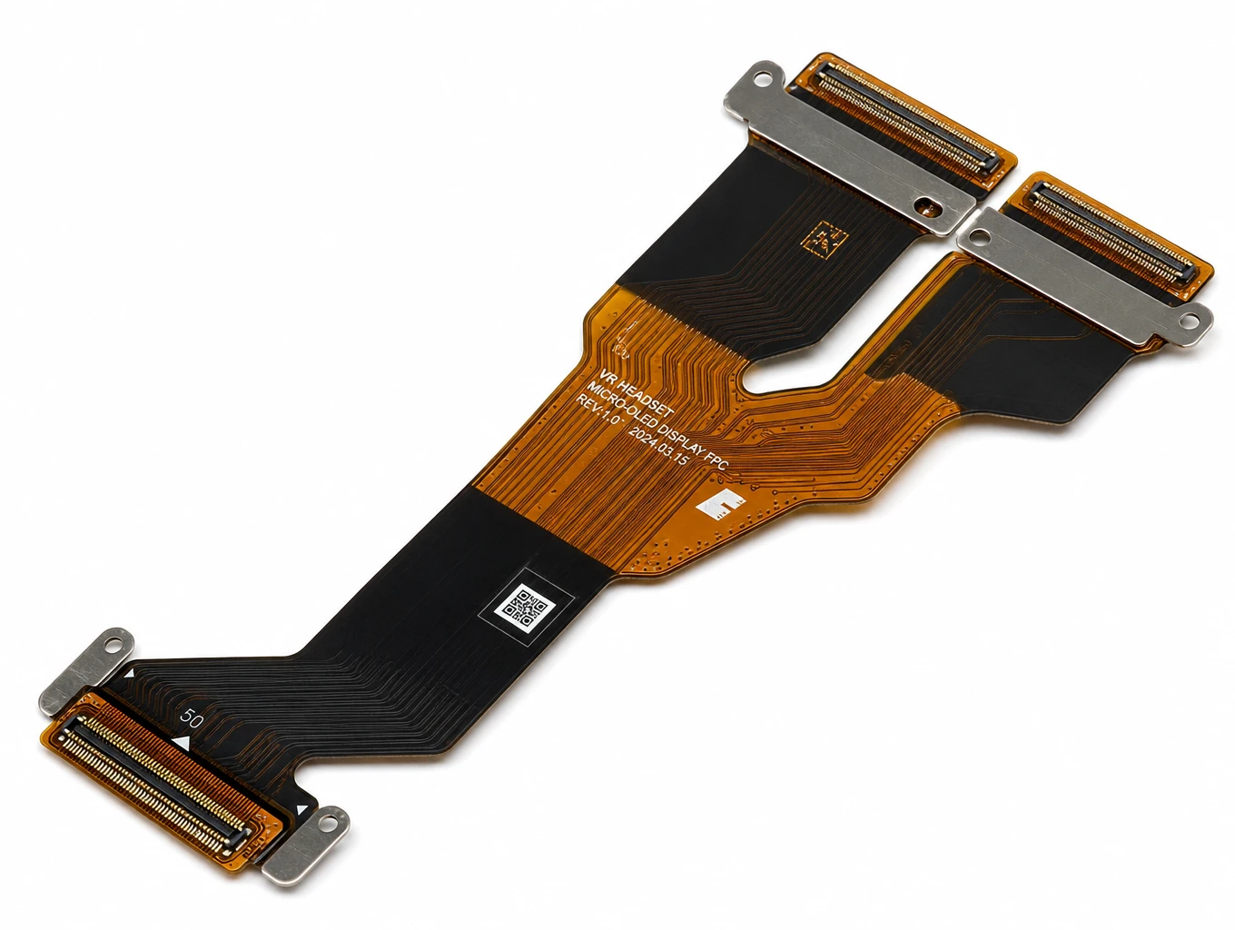
High-Refresh Micro-LED & VR/AR Display FPC
Model: TLX-DFPC-MLED02
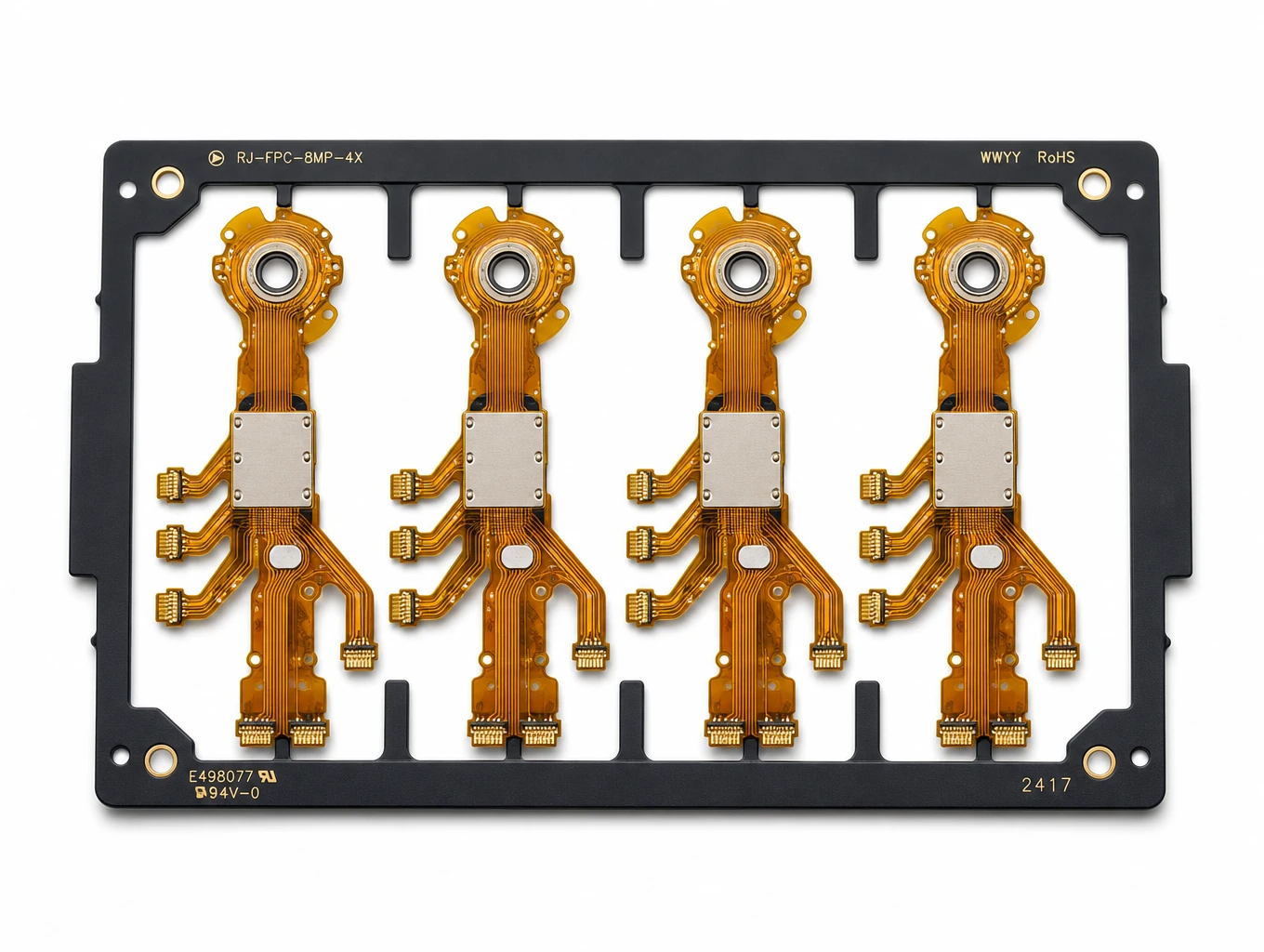
Multi-Branch Humanoid Robotic Joint FPC
Model: TLX-ROB-JNT01
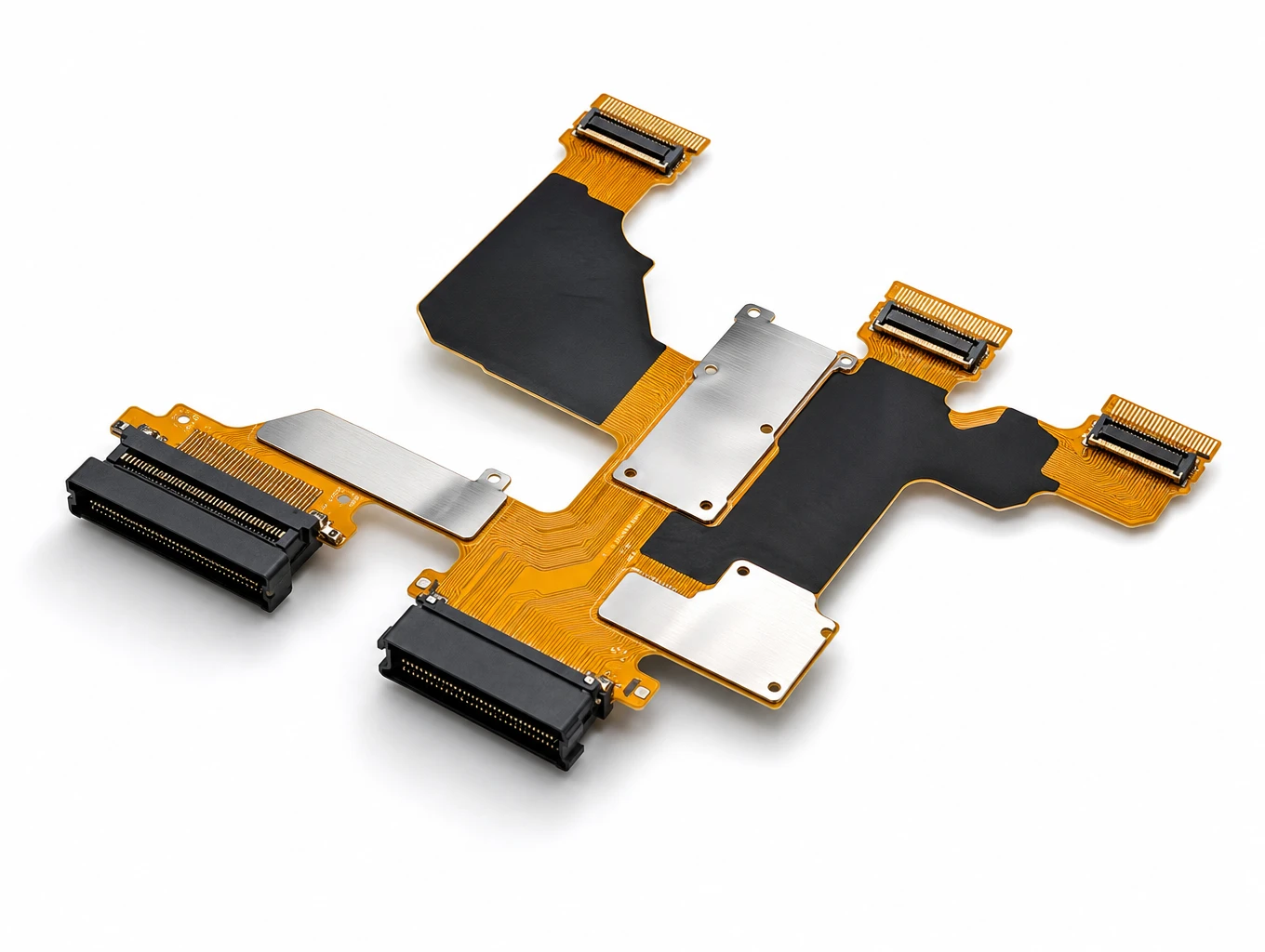
Automotive Curved Cockpit Display FPC
Model: TLX-DFPC-AUTO03
相关解决方案

Display FPC
Teleconix manufactures fine-pitch, high-density FPCs for LCD, OLED, mini-LED displays, camera modules, and optical sensors — delivering stable signal transmission and exceptional brightness control.
Explore Solutions
AI & Robotics & Special Industrial FPC
Overcome severe mechanical stress and extreme spatial constraints in your automated hardware. We design and manufacture custom flexible circuits engineered to endure over 2 million continuous bending cycles in multi-axis robotic joints, bionic grippers, and autonomous AGV/AMR platforms.
Explore Solutions
Smart Automotive Electronics FPC
Teleconix delivers advanced flexible interconnects for ADAS, in-vehicle infotainment, powertrain control, and battery management systems — engineered for performance in intelligent automotive systems.
Explore Solutions
Display FPC
Teleconix manufactures fine-pitch, high-density FPCs for LCD, OLED, mini-LED displays, camera modules, and optical sensors — delivering stable signal transmission and exceptional brightness control.
Explore Solutions
AI & Robotics & Special Industrial FPC
Overcome severe mechanical stress and extreme spatial constraints in your automated hardware. We design and manufacture custom flexible circuits engineered to endure over 2 million continuous bending cycles in multi-axis robotic joints, bionic grippers, and autonomous AGV/AMR platforms.
Explore Solutions
Smart Automotive Electronics FPC
Teleconix delivers advanced flexible interconnects for ADAS, in-vehicle infotainment, powertrain control, and battery management systems — engineered for performance in intelligent automotive systems.
Explore SolutionsFrequently Asked Questions
Conclusion: move from guidelines to an agreed design
Flexible PCB design guidelines are most useful when they lead to clear engineering decisions. Define the application, agree the stack-up and interfaces, and send a consistent RFQ package. Then use prototype results and documented acceptance criteria to decide what is ready for production.
For your next project, start with the application brief and the open-question list rather than an unsupported target price or delivery promise. Contact Teleconix to discuss your flexible PCB requirements and confirm the proposed construction, supply scope and evidence needed for your design. Include the current drawing revision and expected quantities so the conversation can move toward a comparable quotation.