


Introduction
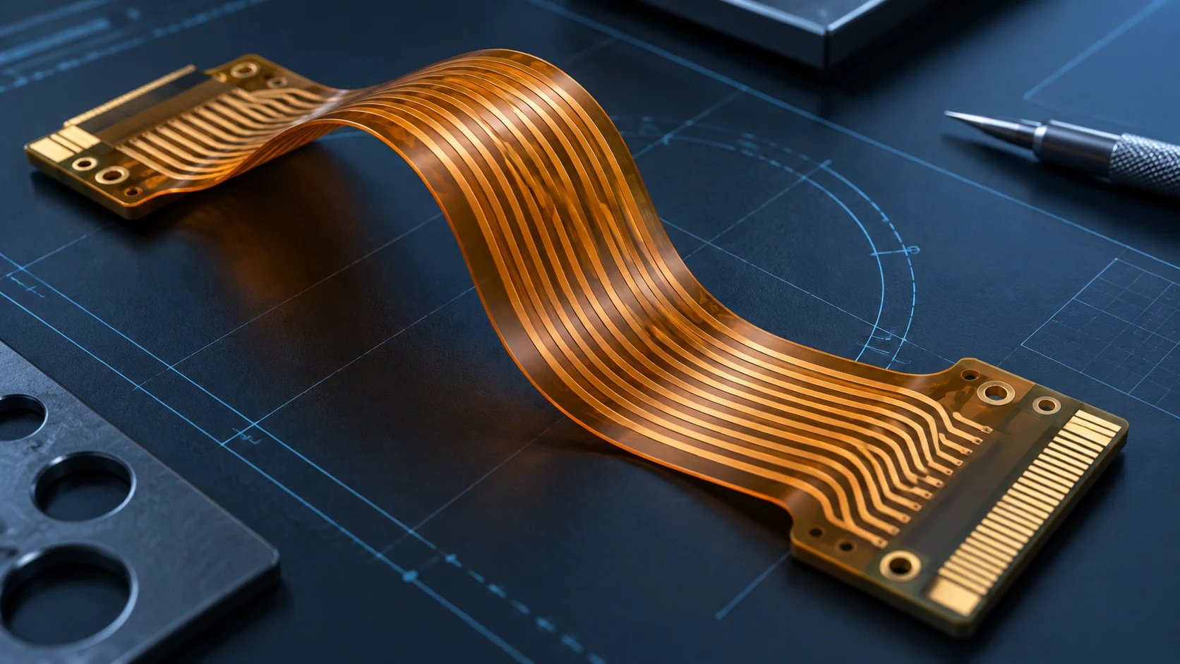
Flex PCB bend radius is a design decision, not a single number copied from a material table. A bend that happens once during assembly has a different risk profile from a loop that moves with every product cycle. The same flexible circuit can survive the first installation and still fail prematurely if its moving span is pinched, creased or pulled at a connector. For OEM teams, the useful question is therefore not only “How small can the radius be?” but “Where is the bend, how often does it move, and what supports it through its full travel?”
This guide turns those questions into a practical review for engineers and B2B buyers. It separates static and dynamic bending, explains the construction and routing factors that change the effective radius, and lists what to put in an RFQ and a prototype test plan. It is a design-review framework, not a certified minimum-radius chart for every build. Final geometry and acceptance criteria should be agreed with the fabricator against the actual material stack, drawing and application.
Start with the bend duty, not a universal radius
The phrase flexible PCB bending radius is often used as though every flex circuit has one permissible value. In practice, the relevant bend is an installed geometry, and the required margin depends on layer count, total thickness, copper geometry, materials, local features and movement. A thin single-layer tail in a fixed fold is not equivalent to a multilayer interconnect sweeping around a hinge. Even within one assembly, a broad loop may have a tighter local point where it meets a clamp.
Start by marking every flex region on a mechanical drawing. Record whether it is folded only during installation, adjusted occasionally for service, or moves in normal operation. Then record the available space at each end of travel, the bend angle, the smallest radius in the actual path, and whether the surface is supported. The governing radius may occur between the nominal end positions; a CAD snapshot of the “open” and “closed” states alone can miss it.
Supplier design guides often show radius-to-thickness ratios as preliminary screening rules. Those are useful for early packaging discussion, but the numbers vary with circuit construction and duty. For example, Minco's flexibility design discussion relates strain to bend radius and circuit thickness and distinguishes flexing applications. Use a supplier's validated guidance for the proposed build rather than treating a published ratio as a production guarantee.
Define the actual decision
- Installation-only bend: Specify the formed shape, sequence and any rework allowance.
- Occasional flex: Describe the expected service movement and number of handling events.
- Repeated motion: Supply the full path, cycle target, speed and supported loop geometry.
The RFQ should name the duty of each zone. “Flexible” by itself does not tell a fabricator whether the design needs a one-time fold or a motion-qualified construction.
Static vs dynamic flex PCB: map the motion
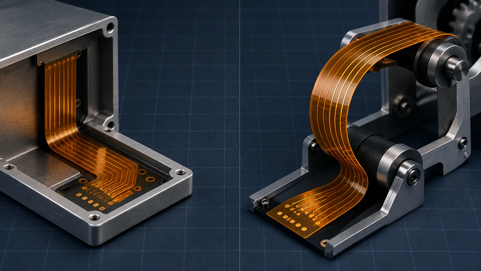
A static vs dynamic flex PCB review begins with how the product uses the circuit. Static flex is normally formed to fit the enclosure and then remains in place. Dynamic flex repeatedly changes shape during normal operation. There are middle cases: a service hinge that is opened a few times, or an installation fold that must tolerate a defined adjustment. These categories are useful only when paired with a clear duty statement.
| Review item | Static or installation bend | Dynamic or repeated bend |
|---|---|---|
| Primary design input | Final installed shape and assembly sequence | Full motion envelope and minimum local radius |
| Handling definition | Number of folds, adjustment and service events | Cycles, speed, dwell, temperature and load |
| 支持 | Form, adhesive or enclosure features that hold the bend | Guides, strain relief and a controlled moving loop |
| Evidence | Assembly trial and electrical check after forming | Application-relevant cycling and electrical monitoring |
A dynamic flex PCB should not be described merely as “able to bend.” Its moving span needs a defined path, while the ends need support so connector solder joints and rigid-to-flex transitions do not become hinges. A cable may visually form a generous loop at rest but tighten under acceleration or when a nearby part changes position. Verify the actual path in the assembled product.
For a fixed fold, a larger radius usually provides more tolerance to assembly variation. If the package forces a tight turn, the engineering response is to revisit stack-up and local geometry with the fabricator. For repeated motion, an apparently acceptable static fold can still be a poor design if the circuit rubs, twists or reverses direction at the same unsupported point.
Stack-up, copper and local features change the bend
As a first-order mechanical idea, a thicker construction develops more strain at its outer surfaces for the same bend radius. That makes total built thickness and the position of conductors important. Copper is not simply a wire drawn on a neutral sheet: traces, plating, pads and layer transitions create local differences in stiffness. Do not infer a safe radius from nominal substrate thickness alone.
Construction choices to review
Ask for the proposed layer count, copper weight, dielectric and coverlay construction, adhesive system, stiffeners and any local plating. A multilayer circuit may be necessary for electrical routing, but placing additional layers through the active bend deserves scrutiny. Where possible, keep the moving zone simple and place complex routing, vias and dense connector geometry in supported areas. A rigid-flex design also needs a deliberate transition between rigid and flexible regions.
Trace routing matters. Avoid abrupt width changes and sharp corners in a bend zone; use smooth paths and keep conductors from concentrating at one edge. Stagger traces on opposite layers where the stack-up and electrical design permit, and discuss the actual bending direction with the fabricator. Through-holes, plated features, exposed pads and solder joints should be moved out of the repeatedly flexing span unless a qualified design specifically accounts for them. These are design-review prompts, not a substitute for the supplier's process limits.
Watch the “invisible” geometry
A stiffener can protect a connector yet create a sharp stiffness transition if its edge lies at the point of motion. A coverlay opening, adhesive edge or copper termination can also localize stress. Mark those boundaries on the stack-up and overlay them on the full motion path. When evaluating a bendable circuit board, ask which portion is intended to flex and which portion must remain supported. The answer is more useful than a generic statement that the board is bendable.
Use the companion flexible PCB materials guide to compare adhesive and adhesiveless laminates, copper foil, coverlay and local stiffeners as one controlled stack.
Design the supported loop and strain relief
The mechanical housing is part of the flex design. A repeatable loop needs room to form without a crease and a path that does not snag, abrade or twist. Keep the bend away from fasteners, hard edges and moving joints that could pinch the circuit. Define the position of clamps and guides relative to the flex and the allowable assembly tolerances, not only the nominal CAD centerline.
At both ends, provide strain relief so motion occurs in the intended flex span rather than at a connector or solder joint. Confirm the clamp does not cut into the coverlay and that the circuit cannot slip into a smaller radius under load. If the housing uses a molded guide, check the entry and exit tangency and the effective radius on the inside of the flex, including tolerance stack-up. A broad nominal guide does not help if the tail leaves it at a sharp angle.
For a robotic joint, a display hinge or an automotive mechanism, the motion may include translation and rotation. A simple two-dimensional side view can conceal out-of-plane twist. Provide the fabricator with an assembly model or photographs of a representative mockup, and call out every point where the flex may contact another part. If the design is still evolving, identify the uncertain dimensions. That lets the team prototype a range of loop lengths and support locations instead of over-committing to a single early drawing.
Teleconix's OEM/ODM collaboration is most useful when the electrical drawing and motion geometry are reviewed together. The related flexible PCB design guidelines checklist covers the broader DFM handoff around stack-up, connectors and revisions.
Build a bend-radius drawing and RFQ package
A manufacturable RFQ translates “bendable flexible PCB” into measurable inputs. Separate product requirements from proposed design choices: the former include motion, envelope and life target; the latter include layer count, materials and routing that may still be optimized. This leaves room for a fabricator to suggest a more robust construction without silently changing the product duty.
| RFQ input | What to supply | 为什么它很重要 |
|---|---|---|
| Motion and duty | Static, service or dynamic; full travel; target cycles and operating conditions | Determines the review and test scope |
| Mechanical envelope | 3D path, end positions, smallest local radius, tolerance and contact points | Exposes pinch and twist risks |
| Flex stack-up | Layers, materials, thickness, copper, coverlay and stiffeners | Sets the construction being evaluated |
| Electrical needs | Netlist, current, impedance or signal constraints and connectors | Prevents a mechanical change from breaking function |
| Acceptance | Inspection, electrical limits, test fixture and sample count to agree | Makes prototype decisions comparable |
Put a revision on the flex drawing and on the mechanical model. Identify whether the marked flex PCB bend radius is an inside radius, centerline radius or a packaging clearance; ambiguity here can turn two seemingly compatible quotes into different builds. Mark bend zones, no-via zones, stiffener edges and connector exits. If a supplier proposes a changed stack-up, ask for an updated drawing before approving tooling.
Procurement should compare quoted designs on the same duty. A lower price for a static-only assumption cannot be fairly compared with a quote built around repeat-cycle qualification. Ask each bidder to state any exception to the motion, materials and validation inputs, then evaluate the exceptions with the design owner. The result is an RFQ that supports a technical decision as well as a unit-price comparison.
Prototype and validate the real assembly
Prototype testing should recreate the product's constraint, not just bend a loose coupon by hand. Install the flex with the intended guides, clamps, connectors and housing clearances. Capture the smallest observed radius through the motion, including start-up, end-of-travel and intermediate positions. Photograph or measure any contact or twist. If the fixture differs from the product, document that difference before interpreting the result.
For an installation-only design, inspect the formed circuit and run the agreed electrical checks after assembly and any defined rework. For repeated motion, create a cycle test plan with travel, rate, duty cycle, temperature range, load, sample size and endpoint criteria agreed before the test. Monitor continuity and relevant electrical performance during or after cycling as appropriate to the application. A passing cycle count is meaningful only for the stated fixture, sample, environment and criteria; it is not a universal lifetime promise.
Flex PCB fatigue testing should also investigate where a failure begins. An open trace near a stiffener edge, intermittent behavior at a connector and abrasion at a guide call for different design changes. Record the failure location, inspection images, electrical observations and drawing revision. If a revision changes loop length, copper geometry or support, repeat the relevant validation rather than carrying the previous result forward by assumption.
Some teams use design guides as a starting point for screening. The final approval belongs to the project-specific build and test evidence. Keep prototype findings in the RFQ revision history so an eventual production quote references the validated construction. This is especially valuable when engineering, purchasing and the assembly partner operate in different locations.
Common failure patterns and practical corrections
A nominal loop becomes a sharp hinge
Look at the assembled device over its full travel. A short tail, tight clamp or poorly placed guide can shift motion to one local point. Rework the loop length, support and entry angle before simply asking for a thinner circuit. A material change without a corrected path may leave the same stress concentration.
The connector carries the motion
If the flex emerges straight from a rigid pad or connector into a moving zone, the transition may see repeated strain. Move the motion away with an appropriately supported exit and verify that the clamp itself does not form a sharp new edge. Review solder joints and stiffener boundaries on the prototype.
A drawing hides assembly variation
Different operators or tolerance combinations can place the same flex in different loops. Provide a forming instruction or assembly aid, specify the acceptable routing window and inspect the first articles. A bendable flexible PCB still needs a controlled installation process.
A test passes without matching the application
A cycle fixture with a smoother path, slower rate or lower temperature than the end product may not answer the design question. Agree on representative conditions and record deviations. When cycle goals are confidential or undecided, use a staged prototype plan rather than implying that an untested design is qualified.
Use a final cross-functional release review
Before release, bring mechanical, electrical, manufacturing and purchasing owners to the same revision. Confirm the bend classification for each zone, the marked geometry, the approved stack-up and the support details. Check that the connector and stiffener drawings match the flex drawing. Review whether electrical performance was measured under relevant motion and whether the test report identifies the exact build and fixture.
Then check the commercial handoff: which changes require requalification, which assumptions were included in the quote, and who approves a substitution. For an OEM program, this prevents a cost reduction or late packaging change from silently altering the validated bend. Teleconix can review a defined package for manufacturability and discuss prototype options; application-level reliability targets and acceptance criteria should be confirmed jointly.
The broader AI and robotics FPC solution illustrates one class of moving-interconnect application. The same review logic applies wherever a compact interconnect must travel in a controlled envelope. Use the checklist above to make the discussion specific to your product, not to infer that one published geometry will fit every program.
Related Products
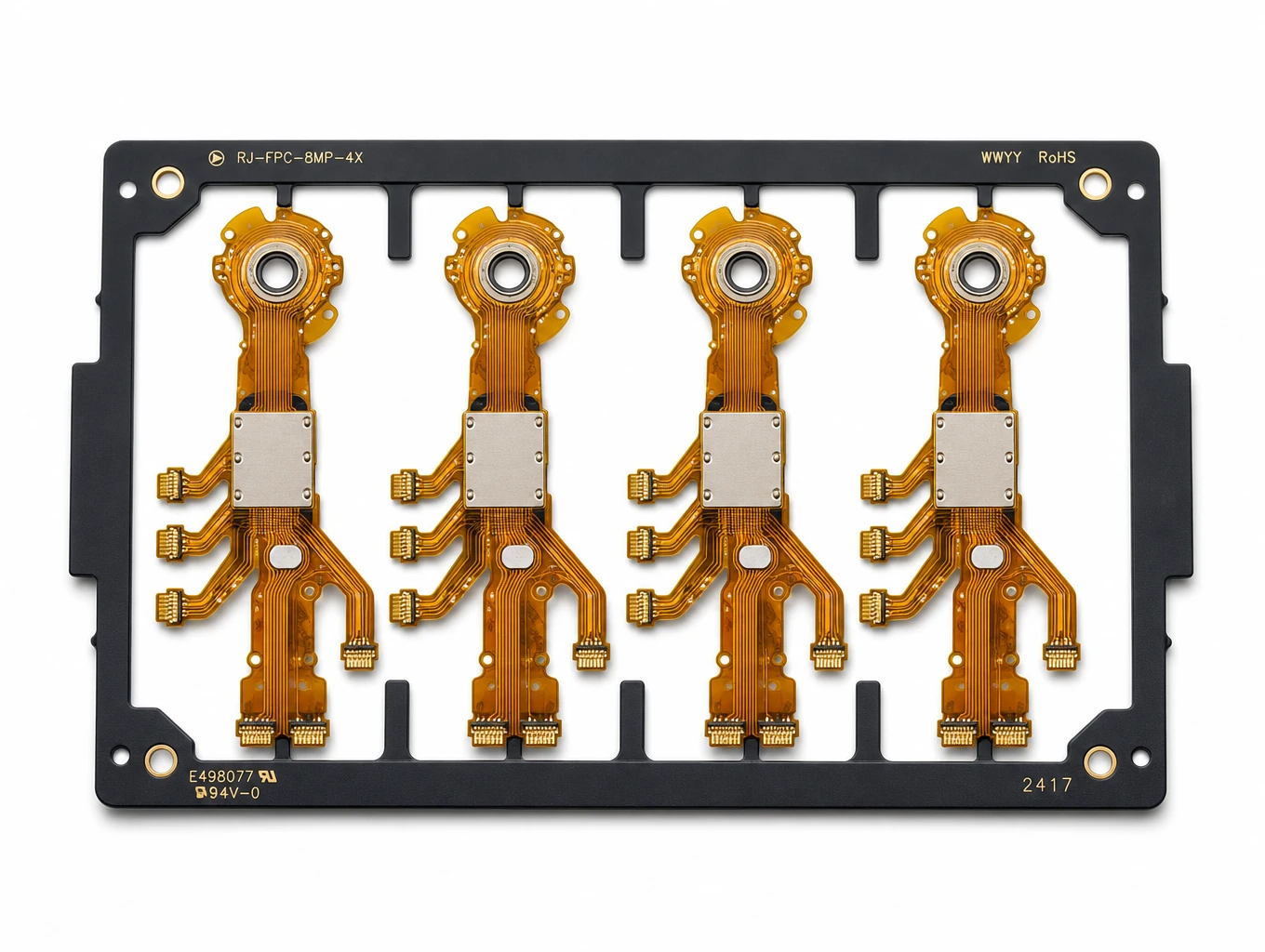
Multi-Branch Humanoid Robotic Joint FPC
Model: TLX-ROB-JNT01
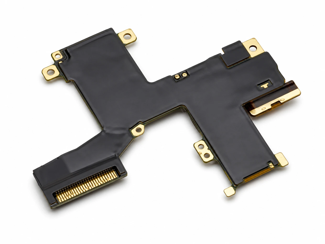
Micro-Form Factor Haptic Surgical Robotics Flex Circuit
Model: TLX-ROB-MED05
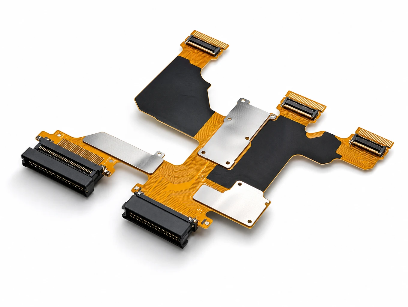
Automotive Curved Cockpit Display FPC
Model: TLX-DFPC-AUTO03
相关解决方案

AI & Robotics & Special Industrial FPC
Overcome severe mechanical stress and extreme spatial constraints in your automated hardware. We design and manufacture custom flexible circuits engineered to endure over 2 million continuous bending cycles in multi-axis robotic joints, bionic grippers, and autonomous AGV/AMR platforms.
Explore Solutions
Smart Automotive Electronics FPC
Teleconix delivers advanced flexible interconnects for ADAS, in-vehicle infotainment, powertrain control, and battery management systems — engineered for performance in intelligent automotive systems.
Explore Solutions
Display FPC
Teleconix manufactures fine-pitch, high-density FPCs for LCD, OLED, mini-LED displays, camera modules, and optical sensors — delivering stable signal transmission and exceptional brightness control.
Explore Solutions
AI & Robotics & Special Industrial FPC
Overcome severe mechanical stress and extreme spatial constraints in your automated hardware. We design and manufacture custom flexible circuits engineered to endure over 2 million continuous bending cycles in multi-axis robotic joints, bionic grippers, and autonomous AGV/AMR platforms.
Explore Solutions
Smart Automotive Electronics FPC
Teleconix delivers advanced flexible interconnects for ADAS, in-vehicle infotainment, powertrain control, and battery management systems — engineered for performance in intelligent automotive systems.
Explore Solutions
Display FPC
Teleconix manufactures fine-pitch, high-density FPCs for LCD, OLED, mini-LED displays, camera modules, and optical sensors — delivering stable signal transmission and exceptional brightness control.
Explore SolutionsFrequently Asked Questions
Conclusion: agree on the motion before the radius
A useful flex PCB bend radius specification starts with duty, construction and a measured path through the actual assembly. Static installation bends and dynamic moving loops call for different support and validation. Keep local copper features and stiffness transitions out of the active bend where the design allows, and record the agreed geometry and test criteria on a controlled revision.
For an OEM review, share your drawings, stack-up, motion envelope and target conditions through the Teleconix contact form. The team can discuss manufacturability and a prototype plan against the actual design inputs.