
Define the acceptance question
Flex PCB electrical testing checks whether an unpopulated flexible circuit has the connections required by its design and adequate isolation between conductors that should remain separate. A useful test plan identifies the design revision, accessible test points, coverage, conditions and disposition rules. That information lets an OEM decide whether a passing result supports release of the delivered lot.
Imagine a compact sensor interconnect with copper lines running through a flexible span and exposed contacts at both ends. One broken line can disconnect a sensor. A copper bridge between adjacent lines can connect channels that the schematic keeps separate. An electrical test addresses both failure modes even when the circuit looks acceptable under magnification.
Read the FPC manufacturing process guide for the wider inspection flow. This guide starts at the point where a buyer asks what a test result covers and what should accompany the shipment. Separate the bare-circuit requirement from acceptance of a populated assembly, a moving mechanism or a complete product. The test plan and delivered report can then say which condition each result represents.
Decide when evidence will be collected
Put each check at a point where the intended feature can be reached and the result can be interpreted. A panel-level test can check accessible nets before singulation. If cutting, reinforcement, attachment or subsequent handling introduces a meaningful failure risk, decide which checks also belong after that step. Record the stage and whether evidence comes from every circuit, selected samples or a representative coupon. This prevents a lot summary from hiding the difference between tested units and sampled features.
Separate continuity from isolation
A continuity check measures the intended path between designated points on a net. An isolation check measures the separation between designated nets that should remain distinct. On the concept layout below, the two pads at either end of the upper trace are on the same net. The upper and lower traces belong to separate nets. A continuity measurement along one path and an isolation measurement between the paths answer different acceptance questions.
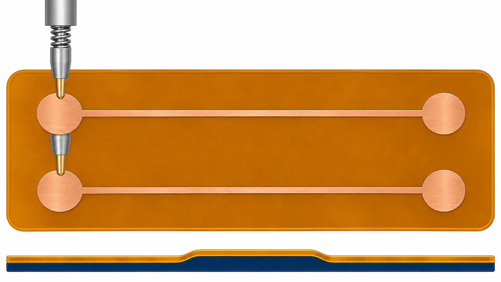
Agree on the maximum allowed resistance for a required path and the minimum acceptable isolation for the selected net pairs, together with the relevant stimulus, dwell time and measurement method. A handheld meter’s audible continuity indication can help a technician localize an issue, while a release record needs the configured thresholds and coverage. Take the limits from the approved drawing, invoked test specification and supplier agreement. The IPC-9252B public contents identifies continuity, isolation, retesting and traceability as distinct topics for unpopulated printed boards. Confirm the applicable revision and agreed test level with the supplier.
Document what a pass does and does not measure
A conductive path can satisfy a specified continuity limit and still require a separate check of current carrying behavior, resistance under motion or controlled impedance. List any such checks in the acceptance matrix with their own methods and limits. High voltage withstand and long-term insulation qualification also require a defined procedure and suitable equipment. Give them separate report entries when the product requires them.
Release a controlled netlist and access map
Give the supplier a testable definition of the circuit. Include the part number, drawing and revision, fabrication data, an agreed design connectivity source, and identification of the intended test contacts. Name the reference that governs when CAM geometry and the electrical connectivity definition disagree. Ask how the tester program is derived, checked and tied to the released files.
For a connector tail, verify the pin-one mark, contact side and mirrored orientation across both the board drawing and any fixture drawing. Nets can change names between the schematic, CAD export and test system. Maintain a cross-reference for names that differ and for any intentional ties or common reference planes. Keep branch endpoints in the access review so a measurement between two convenient pads does not leave a branch unobserved.
Review inaccessible nets with the supplier
A coverlay opening, fine-pitch finger, stiffened area or contact on the opposite side can limit access. Mark the proposed contact points on both faces and identify where probing could mark a mating surface. Confirm board support and local clearances. Discuss whether permitted alternative contacts, a different test stage or a coupon can provide useful evidence for inaccessible features. Record the approved exception and its coverage explicitly. A panel coupon provides evidence about the feature it represents, and the release report should say which checks were performed on the actual units.
Put the design export and test requirement in the same release package. The flexible PCB RFQ file guide explains what to include. If a change affects nets, pad access, connector orientation or stack-up, assess its effect on the approved program and fixture before the next build. Include an approval record for changes that affect coverage or acceptance limits.
Choose probing and support for the part
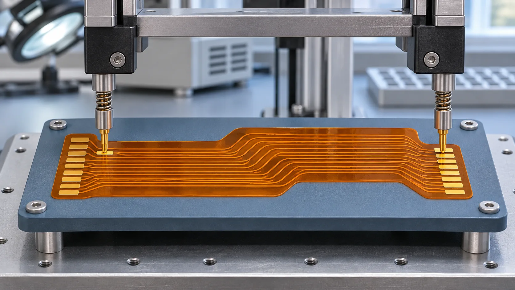
Choose the method by comparing accessible pad geometry, circuit support, test coverage, change frequency and production volume. A moving probe system can apply a program without a dedicated pin fixture for every design. A dedicated fixture can be attractive for repeat builds when positioning, probe access and a stable revision have been validated. HIOKI’s flying-probe tester documentation provides an example of equipment designed to inspect bare boards and flexible substrates. Equipment literature describes that model, while a supplier must confirm the setup and achievable coverage for your part.
The flexible span should lie on stable support so contact force does not shift the pad or bend the circuit unintentionally. Check the orientation feature and locate the part consistently. Ask how the fixture avoids damage to connector fingers, and whether probing uses a different area or dedicated pads when the mating surface is sensitive. For double-sided access, review the relationship between probe positions and support openings. Inspect initial samples for contact marks when that risk matters.
Match resistance measurement to the decision
A routine continuity screen and a precise low-resistance measurement can require different setups. If the acceptance decision depends on a small resistance difference, leads and contacts can matter. A four-wire Kelvin method uses separate current and sense connections to reduce their influence on the measured voltage. Confirm practical access to the intended sense points, the instrument range and the repeatability of contact. A probe landing on the wrong point can still give a misleading result. See Keysight’s four-wire resistance measurement guide.
Compare the proposed methods with the same coverage and acceptance limits before comparing quotes. Ask for the time and cost implications of test point changes, fixture maintenance and program revisions separately from the unit fabrication price.
Review first failures before releasing the lot
A first failure is evidence to preserve. Save the failing unit or panel position, net pair, measured value or indication, fixture and program revision, and the stage where it occurred. Follow the agreed containment rule for the affected population. If a retest passes after reseating the part, document the original failure, what changed and the basis for release. Require a disposition from the responsible party when the cause remains unresolved.
| Observed result | First review | Evidence to retain |
|---|---|---|
| Open or high resistance on one path | Check contact, program mapping and the intended path. Localize the failure if it repeats. | Net and pad IDs, measured value, unit position and retest record. |
| Low isolation between two nets | Review intended ties, contamination, handling and visible bridging. Compare the same pair under the approved conditions. | Net pair, stimulus, dwell, measured value and inspection notes. |
| Similar fail pattern across a panel | Compare panel positions, fixture alignment and the current program against the released data. | Failure map, alignment check and confirmed program revision. |
| Passes flat, fails during movement | Check the installed route, probe or connector movement and the flex region under the agreed motion condition. | Motion setup, monitoring threshold, event log and failure location. |
Consider a repeated open at the same pin on several parts. A reversed fixture mapping can produce the same pattern as a common fabrication defect. Compare the pin map and check the contact system before changing a drawing or accepting the lot. Once the test setup is confirmed, compare the failure to inspection data for the same position. Keep the diagnosis and release decision in the lot record, including any approved deviation and its affected quantity.
Plan assembly, motion and signal tests separately
A bare circuit can pass and later develop a fault during assembly or installation. Add acceptance checks where connectors, soldering, reinforcement or routed bends introduce a new failure mode. Define the assembly configuration, connector part numbers and installed route on the test drawing. Keep the bare-board result alongside the populated assembly or functional result so teams can see when the failure first appeared.
For a moving circuit, monitor the installed path
If operation repeatedly moves the interconnect, describe the representative motion, bend support, fixture orientation, stroke and environmental conditions. Agree on which nets are monitored, the resistance or interruption criterion and the monitoring rate or event detection method. Brief opens during movement may escape a flat before-and-after measurement. Link the test to the actual construction and motion envelope. Record the number of units tested and any interruption position. The flex PCB bend radius guide covers how installed geometry and bend duty affect this plan.
For high-speed nets, define an impedance check
Continuity is a DC connectivity check. A transmission line’s characteristic impedance depends on geometry, dielectric layers and its reference path. If controlled impedance is specified, agree on the target, tolerance, stack-up, representative test structure and measurement method. A TDR result should identify which structure and portion of the trace were measured. Keep the test fixture or launch effects in mind when interpreting a local excursion. See the controlled impedance flex PCB guide for stack-up and coupon planning.
Assign ownership of each stage before quoting. Define whether the fabricator, assembly supplier or OEM runs the check and who approves deviations. If multiple suppliers contribute evidence, align part revisions, lot identifiers and the handoff record so a passing result can be traced to the units delivered.
Ask for a report you can audit
Request a sample report before ordering if acceptance depends on traceability or detailed results. A lot report should identify the part number and drawing revision, lot or serial range, date, test stage and responsible party. Include the tested quantity, pass and fail counts, covered features, test program revision, fixture or equipment identifier, and applicable criteria or their controlled reference. If individual measurements are required, specify which values to retain and how they map to the delivered units.
Distinguish direct test results from a statement of conformance. A conformance statement can be suitable when its underlying test scope is agreed and records are available. For first articles or unusual failures, a measured value or test log may be more useful. Agree on retention, file format, lot matching and how missing records affect release. A report covering only a panel should state whether its identifiers can be traced to each separated circuit.
Use one acceptance matrix across suppliers
Record the required test, unit or sampling basis, limits, evidence type and approving owner in one table. Assign the same part and revision identifiers to the CAD package, purchase order and supplier report. Provide clear instructions for intentional exceptions, inaccessible points and rework. If a prototype was screened with moving probes and the production lot uses a fixture, require verification that the production program covers the same approved features and preserves the same acceptance decision.
Before releasing a build, walk through one example from a drawing net to a test result and one from a failing unit to its disposition. That review exposes gaps in test access, reporting or lot identification before they delay acceptance. Use the flexible PCB prototype validation guide to connect electrical acceptance with mechanical and assembly evidence.
Agree the release checklist before the build
Use the following checklist for a supplier review. Bring the design and quality owners together when an acceptance decision depends on both the mechanical support and electrical test scope. Settle open questions at first article review, then carry the approved decisions into the production package.
- Design baseline: released drawing and fabrication data, approved connectivity source, intentional ties and pin mapping.
- Test access: pad coordinates, side and orientation, support method, approved contacts and coverage exceptions.
- Electrical criteria: continuity and isolation requirements, conditions, method, test stage and sampling or unit coverage.
- Failure handling: first failure evidence, retest rules, containment and approval for any accepted deviation.
- Release evidence: tested quantity, lot or unit identifiers, program revision, results and retention.
- Separate validation: assembly function, installed motion, impedance or environmental checks where required.
Use the checklist to compare what each quote includes. Two quotes can both say electrical test while differing in per-unit coverage, isolated net pairs, retained data and fixture setup. Resolve differences by asking the supplier to annotate the same drawing and return the proposed method and deliverables. A clear scope also helps engineering judge whether a lower-cost method leaves a risk that needs a separate check.
At change review, ask which design inputs, tools and acceptance records will be affected. Trace width, coverlay openings, pin mapping and fixture contact points can change independently. Record the update at the relevant level and request first article evidence where appropriate. Keep approved versions accessible to purchasing, engineering and quality so each team evaluates the same build and test scope.
Related Products
Industrial HMI & TFT-LCD Module FPC
Model: TLX-DFPC-IND05
High-Speed ADAS Multi-Camera SerDes FPC
Model: TLX-AUTO-ADAS02
Wearable Smartwatch & Round AMOLED FPC
Model: TLX-DFPC-WEAR04
Related Solutions

Display FPC
Display FPC products for OLED, AMOLED, micro-LED and TFT-LCD modules in handheld, wearable, automotive and industrial devices. Review the display interface, connector and installed flex shape together.
Explore Solutions
AI & Robotics & Special Industrial FPC
Flexible circuits for robotic joints, vision sensors, actuators and industrial interfaces. Match the circuit route to the motion, electrical connections and enclosure of your machine.
Explore Solutions
RF & Communication FPC Solutions
Custom RF flexible PCB and telecom interconnects for antenna modules, wireless terminals and high-speed communication assemblies. Coordinate materials, signal paths, shielding and connector support with Teleconix before prototype release.
Explore Solutions Display FPC
Display FPC products for OLED, AMOLED, micro-LED and TFT-LCD modules in handheld, wearable, automotive and industrial devices. Review the display interface, connector and installed flex shape together.
Explore Solutions AI & Robotics & Special Industrial FPC
Flexible circuits for robotic joints, vision sensors, actuators and industrial interfaces. Match the circuit route to the motion, electrical connections and enclosure of your machine.
Explore Solutions RF & Communication FPC Solutions
Custom RF flexible PCB and telecom interconnects for antenna modules, wireless terminals and high-speed communication assemblies. Coordinate materials, signal paths, shielding and connector support with Teleconix before prototype release.
Explore SolutionsFrequently Asked Questions
Prepare the electrical test package
Start with a released netlist, a map of accessible pads and a short acceptance matrix. Define the continuity and isolation limits with the test conditions, agree on first-failure handling, and ask how the results follow each shipment. Set additional checks for populated assemblies, installed movement or controlled impedance when the application calls for them.
For an OEM build review, share your flex circuit drawings and test requirements with Teleconix. Include the part revision, planned volumes, connector orientation, and which measurements or reports your team needs at first article and production release. The engineering review can then focus on the proposed construction, test access and evidence needed for the specific project.