
Introduction
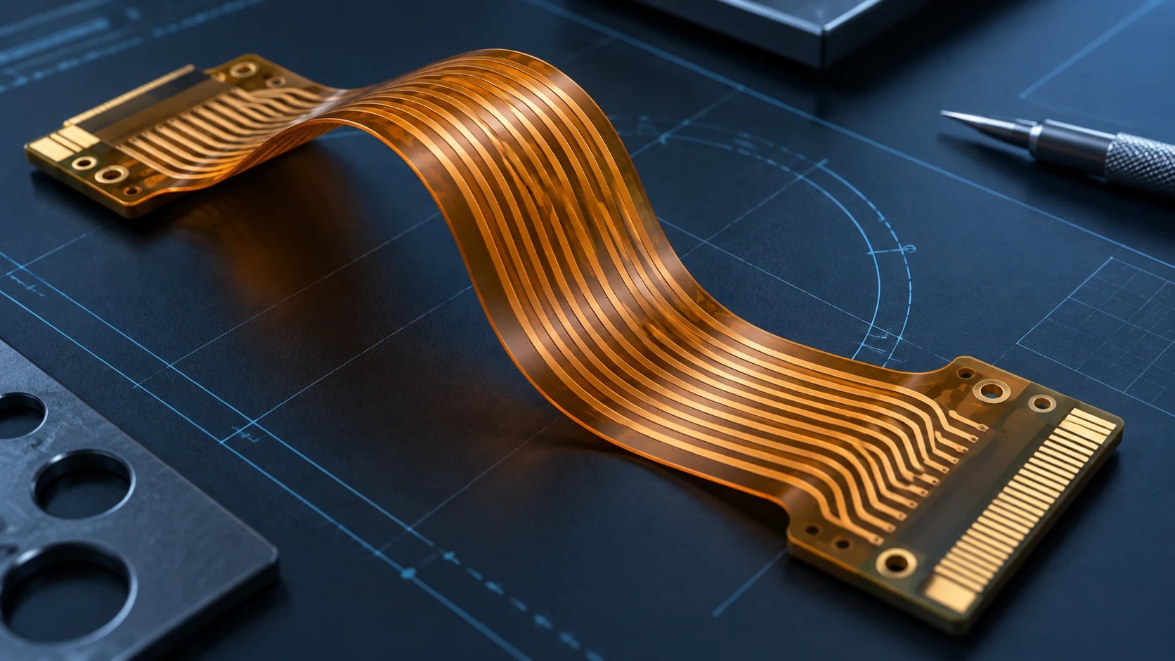
A flexible PCB prototype should answer a specific engineering question before it becomes an order for more parts. Does the circuit fit the enclosure? Can the connector be assembled without damaging the tail? Does the installed circuit carry the required signals while bending in the intended way? A sample that works flat on a bench may leave these questions unanswered.
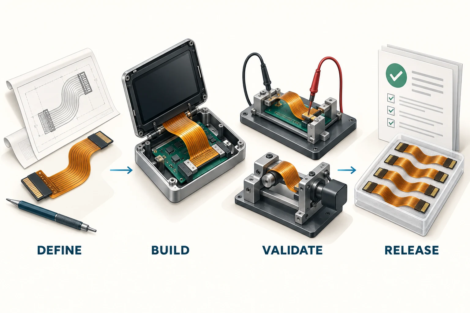
For OEM engineering and purchasing teams, the most useful prototype program connects one released design package to a documented build, a practical validation plan and a clear production decision. This guide explains what to prepare, what to inspect and how to compare sample quotations without confusing a quick delivery with a qualified product.
Start with the FPC basics guide if the team still needs to distinguish bare flex, assembled FPC and rigid-flex. Then use the steps below to define what the first build must prove.
Define what the prototype must prove
Write a short objective before requesting samples. A mechanical fit model, an electrical demonstrator and a production-representative prototype serve different purposes. Combining them under one vague instruction can lead to unnecessary cost or a misleading approval. Name the decision that the build will support and the evidence needed to make it.
A fit sample may establish outline, installation sequence and connector access. A functional sample may establish the electrical interface. A production-representative build should also use the agreed construction and processes, or explicitly identify every difference. A substitute film or different reinforcement may be acceptable for an early trial, but its limitations must accompany the results.
Assign an owner to each objective. Mechanical engineering can approve routing clearance, electronics can approve function, manufacturing can review assembly and quality can check records. Purchasing should coordinate these requirements into one scope so a supplier is not asked to resolve conflicting acceptance criteria after fabrication.
For diagnostic or monitoring equipment, extend the prototype review to the installed sensor interface, housing route and documented exposure conditions. The medical device FPC integration and test guide shows how to connect those application requirements with an OEM verification plan.
Prepare a controlled prototype RFQ package
Provide the fabrication data, a dimensioned drawing and a clear revision identifier. The drawing should identify the outline, connector orientation, critical dimensions, contact exposure, supported areas and intended bend zones. A three-dimensional view or installation sketch helps explain routing that a flat outline cannot describe.
Define whether the order covers a bare circuit, populated assembly or tested module. For assembly, include the BOM, manufacturer part numbers, approved alternatives, component placement information and agreed test requirements. Resolve conflicting file revisions before release; a newer drawing paired with older copper data creates an avoidable ambiguity.
An RFQ should also state quantities, delivery format, requested records, packaging needs and the date at which samples are actually needed for engineering work. Ask the supplier to list assumptions and exclusions in its quotation. A written response makes omissions visible before they become a schedule or cost dispute.
- Fabrication data and netlist, where required by the agreed test method.
- Stack-up, materials, finishes, reinforcement and tolerances.
- Installed geometry, bend duty and mating connector details.
- Assembly scope, inspection criteria and deliverable records.
If the samples include mounted components, the FPC assembly planning guide helps define the BOM, placement data, mechanical support and test responsibilities before the build.
Use the flexible PCB RFQ manufacturing file checklist to organise circuit exports, construction drawings, assembly responsibilities and revision control before requesting your prototype quotation.
Agree the stack-up before releasing tooling
A prototype drawing should define more than a nominal finished thickness. Copper, dielectric, adhesive, coverlay and local reinforcement determine how the circuit behaves. Two samples with similar overall thickness can differ in flexibility, assembly compatibility and connector fit. Record the proposed construction and obtain an engineering review before fabrication begins.
Use the flexible PCB materials guide to organize the material questions. If an exact material is unavailable, ask the supplier to identify its proposed alternative and the properties that change. Approval should specify which tests remain meaningful and which require a later build with the production material.
Keep unsupported claims out of the sample specification. A material trade name alone does not establish the complete circuit performance, and a successful single bend does not establish repeated-flex life. Agree tolerances and allowable changes at the circuit level, including local thickness where a connector or clamp engages the part.
Review the connector and stiffener as one interface
Connector problems often appear during installation rather than bare-board inspection. Confirm contact pitch, orientation, exposed contact length, surface finish and the thickness accepted by the mating connector. Check the manufacturer’s current drawing for the exact connector part number rather than assuming all connectors with the same pitch accept the same tail.
The stiffener location matters as much as its thickness. It should support the intended insertion or attachment area without placing an abrupt transition in an active bend. Consider access for fingers or tooling, connector latch travel and the direction in which an operator applies force. A prototype should reproduce these constraints.
Record the connector and stiffener combination used in testing. If either changes later, determine whether insertion, retention and routing checks must be repeated. A tail that fits a development connector does not automatically qualify a different production connector, even if both appear to have an identical footprint.
Validate the installed bend and assembly sequence
A flat electrical test cannot show whether the FPC can be routed through the finished product. Assemble the prototype in a representative enclosure with the actual clamps, connector positions and nearby components. Inspect clearance during installation as well as after assembly. Temporary folding to reach a connector can be more severe than the final shape.
Separate static installation bends from repeated motion. Define the motion path, radius, angle, cycle requirement, speed and environmental conditions for a dynamic application. Include twist, tension and contact with surrounding parts where they occur in the real mechanism. A simplified fixture should document what it omits.
The flex PCB bend radius guide provides a framework for describing those conditions. Avoid adopting a universal bend ratio or lifetime claim without reviewing the actual stack-up. Photograph the routing and support points so the tested configuration can be reproduced by the next team.
Match sample quantity to the validation plan
There is no useful universal sample quantity for every flex circuit prototyping project. Begin with the checks that consume samples, the assemblies needed by each team and the possibility of destructive analysis. Allocate samples deliberately instead of distributing the entire lot informally and discovering that none remain for comparison.
Keep separate groups where one test could influence another. A circuit repeatedly flexed or exposed to a harsh environment may no longer represent an unused sample for baseline measurements. Identify each specimen and record its history. Retain agreed reference samples when they will help investigate later differences.
Small sample results should be interpreted within their limits. A few successful assemblies can identify obvious design problems, but they do not by themselves demonstrate production yield or population reliability. If a statistical demonstration is required, have the responsible quality or reliability team define the sample plan and acceptance logic.
Distinguish electrical test from functional validation
Bare-circuit electrical testing checks the agreed connectivity requirements. It does not necessarily verify the assembled device, signal performance, connector behavior or operation during movement. Specify the required test coverage and report format rather than using “tested” as a complete acceptance criterion.
Functional validation uses the intended electronics and operating conditions. Confirm polarity, power paths, interface behavior and any sensitive signals with an appropriate fixture. When impedance is a requirement, agree the target, tolerance, construction and verification method before fabrication. A coupon result and end-product performance answer related but different questions.
Record the test configuration, equipment identification, software or firmware version where relevant, and the pass criteria. If a sample passes only after a wiring change or manual rework, document that fact. The result belongs to the modified configuration and must not silently approve the original released drawing.
For battery-monitoring samples, use the automotive FPC BMS and sensor design guide to connect the channel map, sensor retention and installed checks to the prototype acceptance plan.
Use a practical sample acceptance checklist
The receiving team needs an acceptance checklist that matches the prototype objective. Review the delivered revision and records first, then inspect the physical parts before assembly. Capture concerns while the samples are still traceable and their handling history is known.
| Review area | Question to resolve | Record to retain |
|---|---|---|
| Identity | Does the lot match the released revision? | Part and lot identification |
| Geometry | Do outline, contacts and supported areas fit? | Critical dimension results |
| Electrical | Was the agreed network and function checked? | Test scope and results |
| Installation | Can the circuit be assembled without unintended strain? | Routing photos and observations |
| Changes | Which deviations or rework affected the samples? | Approved change list |
Keep the checklist proportionate to risk. A missing cosmetic preference and a connector interference should not be treated as equivalent findings. Assign an owner and disposition to each open issue, then state whether the build is accepted, conditionally accepted for a limited purpose or requires another revision.
Ask what changes between prototype and production
A prototype can be built using a route that differs from the proposed volume process. Ask about panel layout, tooling, fixtures, material availability, assembly support and inspection coverage. The purpose is to identify which sample results transfer to production and which assumptions still need confirmation.
The FPC manufacturing and quality guide explains how fabrication steps connect to controlled inputs and records. Request a written list of planned changes before the next build. Changes that affect critical characteristics should receive an engineering decision and an appropriate verification plan.
A pilot lot can help evaluate repeatability, handling and production documentation after the design is stable. Its scope should be defined rather than treated as an automatic extension of a prototype approval. Keep design approval, process readiness and commercial release as distinct decisions, with the responsible people named for each.
Compare prototype quotations on the same scope
Separate recurring part cost from tooling, engineering work, fixtures, assembly and documentation. Ask whether those charges are reusable on the next revision or repeat order. A quotation for bare flex cannot be compared directly with a quotation that includes populated assemblies and functional testing.
Clarify what happens if the design changes after review. Outline changes may affect tooling; connector changes may affect assembly fixtures; a revised stack-up may affect material planning. The quotation should explain how these changes are handled without assuming that every later revision is included.
Use the flexible PCB cost and quotation guide to normalize the comparison. Evaluate the cost of obtaining a usable engineering result, including any missing test work your own team must perform. A lower sample price can lose its advantage if the delivered construction cannot support the planned validation.
Build a realistic schedule without shortcut assumptions
A prototype schedule includes more than fabrication time. File review, question resolution, material planning, tooling, assembly, test, shipping and incoming evaluation all affect the date when useful results become available. Confirm what event starts the supplier’s quoted clock and what deliverable ends it.
For an urgent request, identify which constraints are flexible. An early mechanical model might be useful before the electrical sample, but it must be labelled for that purpose. Do not accept undocumented substitutions merely to preserve a date if they prevent the prototype from answering its original engineering question.
Ask for an agreed schedule based on the actual package and supplier confirmation. Avoid treating a generic “quick turn” statement as a guaranteed service level. Include time for the OEM to answer DFM questions and assess the samples, because a late engineering decision can consume the time saved in fabrication.
Control revisions and close the feedback loop
Maintain one issue log linked to the sample identifiers and released revision. Describe the observation, operating condition, suspected cause, proposed action and verification needed. Separate a confirmed design problem from a handling event or an unresolved hypothesis so the next build addresses the right cause.
When revising the circuit, update every affected document and identify what changed. A connector orientation change may require new assembly information as well as new fabrication data. The supplier should acknowledge the complete release rather than relying on an email attachment whose revision conflicts with the drawing.
Compare the revised samples against the same relevant criteria and record why any test is omitted. Do not close an issue solely because the visible symptom disappeared once. If the root cause remains uncertain, retain that uncertainty in the release decision and plan further work proportionate to the application.
Prepare the handoff from prototype to production
Before repeat orders, assemble the approved drawing, stack-up, fabrication data, BOM where applicable, inspection requirements, accepted deviations and sample results. Define the delivery and packaging format. Include handling instructions when the circuit can be damaged by unsupported lifting, creasing or an incorrect insertion sequence.
Agree how future material, tooling, process or subcontract changes will be communicated. Identify the records required with each lot and the route for addressing nonconforming material. The first production purchase order should point to the controlled package rather than an old prototype quotation with unresolved assumptions.
For a project discussion with Teleconix, use the OEM and ODM inquiry workflow to present your sample objectives and available design files. Request confirmation of the proposed build scope, materials, tests, quantities and schedule. Keep the final commitments tied to the reviewed project rather than a generic prototype description.
Example: turn a display tail problem into a testable brief
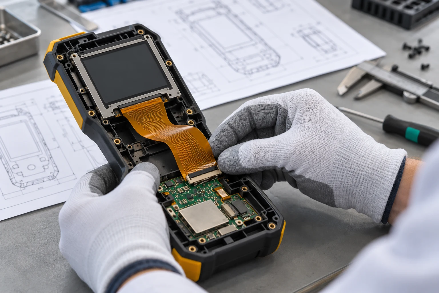
Consider an illustrative handheld instrument with a display connected to its main board by an FPC. The first development sample operates correctly outside the enclosure, but technicians struggle to close the housing without pushing the tail against an internal rib. Ordering a larger batch of the same sample would repeat an unresolved assembly problem.
The next brief should identify the connector positions, housing clearance, installation sequence and allowable routing envelope. Mechanical engineering can update the installation sketch, while the supplier reviews whether the outline, supported areas or stack-up should change. The team should distinguish a design change from a temporary assembly workaround.
Validation then needs both electrical operation and an installation trial with the relevant enclosure revision. Record the route before closing the housing, inspect any contact points and confirm that the connector remains properly engaged. If service access requires reopening the product, include that operation in the review rather than assuming installation happens only once.
The acceptance decision should name the tested configuration and unresolved items. This example does not establish a general bend radius, sample count or pass limit. It shows how a clear objective turns a vague request for better flexibility into specific files, observations and decisions that can be carried into the next build.
For a display-tail project, use the Display FPC integration checklist to close pin mapping, connector fit and installed-route questions before the prototype build.
Related Products
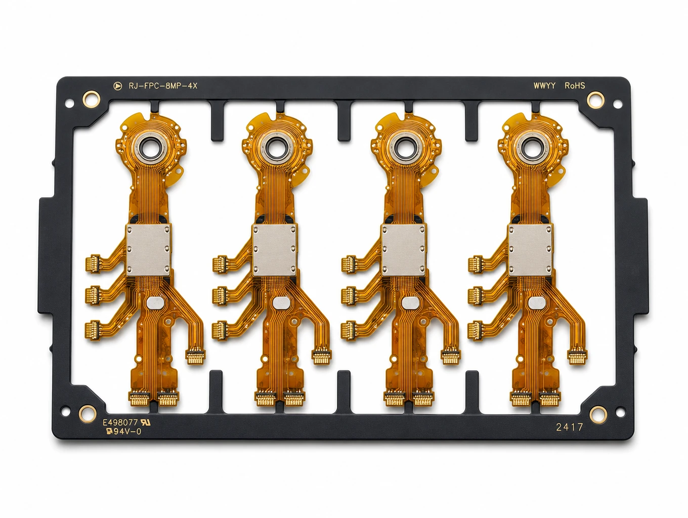
Multi-Branch Humanoid Robotic Joint FPC
Model: TLX-ROB-JNT01
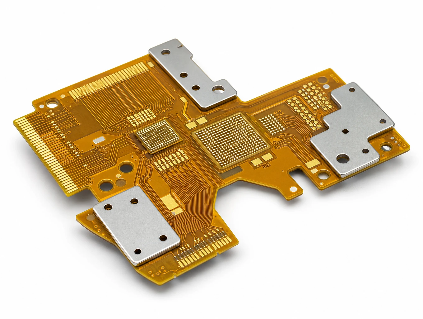
400G/800G High-Speed Optical Transceiver Multi-Layer Flex PCB
Model: TLX-COMM-OPT03
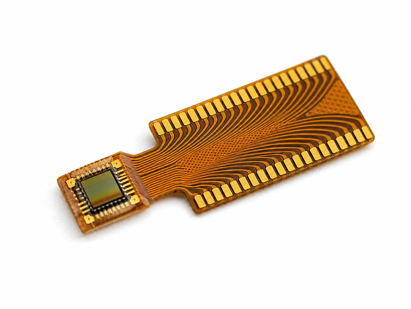
Medical Endoscope Micro-Display FPC
Model: TLX-DFPC-MED06
Related Solutions

AI & Robotics & Special Industrial FPC
Flexible circuits for robotic joints, vision sensors, actuators and industrial interfaces. Match the circuit route to the motion, electrical connections and enclosure of your machine.
Explore Solutions
Smart Automotive Electronics FPC
Automotive FPC products for battery monitoring, ADAS cameras, radar, cockpit displays, steering controls and LED lighting. Select a starting configuration by module function and installation needs.
Explore Solutions
Display FPC
Display FPC products for OLED, AMOLED, micro-LED and TFT-LCD modules in handheld, wearable, automotive and industrial devices. Review the display interface, connector and installed flex shape together.
Explore Solutions AI & Robotics & Special Industrial FPC
Flexible circuits for robotic joints, vision sensors, actuators and industrial interfaces. Match the circuit route to the motion, electrical connections and enclosure of your machine.
Explore Solutions Smart Automotive Electronics FPC
Automotive FPC products for battery monitoring, ADAS cameras, radar, cockpit displays, steering controls and LED lighting. Select a starting configuration by module function and installation needs.
Explore Solutions Display FPC
Display FPC products for OLED, AMOLED, micro-LED and TFT-LCD modules in handheld, wearable, automotive and industrial devices. Review the display interface, connector and installed flex shape together.
Explore SolutionsFrequently Asked Questions
Conclusion: approve evidence before repeating the build
A successful flexible PCB prototype connects the intended application to a controlled build and a recorded decision. Define the purpose, release consistent files, validate the installed circuit and identify every difference from the proposed production route. This makes the next revision or purchase order easier to justify.
Share the drawing revision, stack-up, bend conditions, assembly scope, sample quantities and planned tests through the Teleconix project inquiry form. Ask for a project-specific review of the open questions before authorizing the build. A clear prototype brief gives engineering and purchasing a common basis for moving forward.