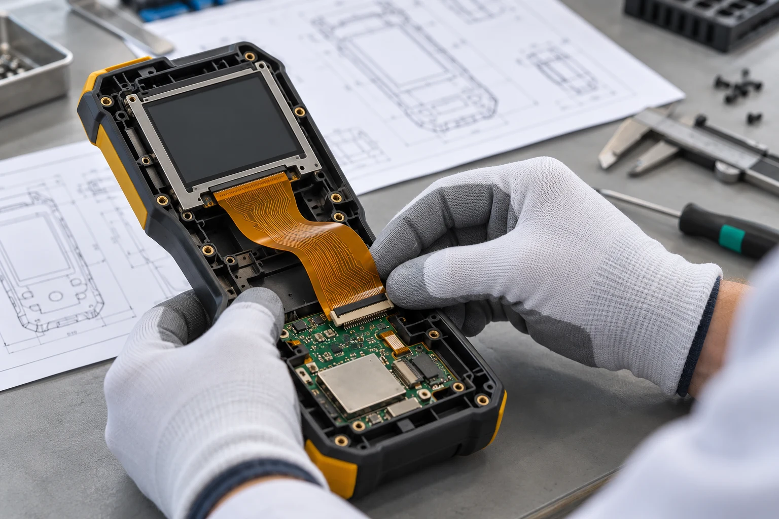


A flexible PCB RFQ should define a quotable revision
A flexible PCB RFQ should let engineering, purchasing and the supplier identify the same circuit, construction and delivery scope. A copper image alone rarely answers every quotation question. The package also needs a controlled outline, material and thickness requirements, flex-specific details and a clear statement of what must be delivered.
Start by deciding whether you need an early budget estimate, a prototype quotation or a production offer against released files. Mark unresolved requirements explicitly. A supplier can then explain its assumptions instead of silently filling gaps that later become manufacturing or acceptance disputes.
This guide provides an OEM file checklist, a package structure and a method for resolving technical questions before an order. Use it alongside the flexible PCB design review checklist. It focuses on the information exchanged during procurement; the actual construction, service scope and acceptance criteria still need agreement for the individual project.
Separate a budget estimate from a production release
An early estimate may begin with an outline, approximate quantities, proposed layer construction and an application description. State which inputs are provisional and ask the supplier to list the basis of the estimate. A budget number built around an assumed material or panel arrangement should remain identifiable as conditional.
A production quotation needs enough detail to resolve the features that affect the manufacturing route, inspection and delivered configuration. Give the circuit part number and revision, drawing revision, required quantities and requested delivery destination. Identify whether the requirement is a bare circuit, a supported circuit with attachments, or an assembled flexible circuit.
Do not label a package ready for production while connector thickness, a bend region or an acceptance test remains undecided. Record an owner and closure date for each open item. Purchasing can request a conditional offer, but the purchase order should reference the final approved package and the supplier’s accepted deviations.
Use a file checklist that matches the order scope
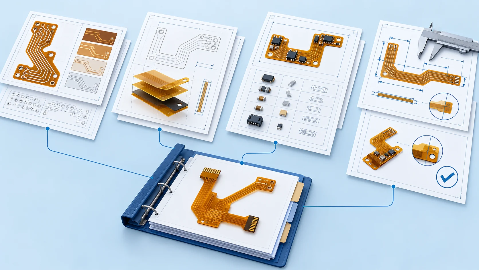
The following flexible PCB quotation checklist is a practical starting structure. It is not a universal list of mandatory file extensions. Confirm the accepted formats and the level of detail with the supplier before sending proprietary design data.
| Package group | Include | Question to close |
|---|---|---|
| Identity and scope | Part number, revisions, quantities and bare or assembled scope. | What exact configuration is priced? |
| Circuit geometry | Copper, protective openings, outline and drilling or routing data. | Do the files describe one aligned circuit? |
| Construction | Stack-up, materials, copper, finish and local thickness requirements. | Which proposal requires approval? |
| Flex details | Bend regions, contact geometry, coverlay and reinforcement drawings. | How will the circuit fit and be handled? |
| Assembly, if included | BOM, placement, assembly drawings and sourcing responsibilities. | Who supplies, fits and verifies each item? |
| Acceptance and delivery | Inspection, testing, documentation, packaging and delivery basis. | What evidence and deliverables are included? |
For each group, name the authoritative file and its revision in a manifest. Where two files intentionally show different information, explain their roles. For example, an installed mechanical view may show a formed circuit while fabrication artwork describes the flat circuit. That difference should be explicit rather than left for a CAM engineer to interpret.
A missing item is easier to discuss when it is listed as open. If the design has no components, mark assembly data not applicable. If impedance has not been defined, identify the electrical owner. Avoid filling an empty field with an unsupported standard value simply to make the package look complete.
For example, a sensor interconnect package might contain a complete copper export but no approved connector-tail thickness. Mark that thickness as an engineering question and attach the connector drawing. Ask for a proposed construction and the finished measurement location. Once approved, update the drawing and manifest so that the quotation, sample inspection and production order all reference the same requirement.
Export and inspect the actual fabrication data
For flex PCB Gerber requirements, confirm the format your CAD system exports and the supplier can import. Ucamco describes Gerber layer images and the additional manufacturing information carried by a Gerber Job file. Its Gerber Job overview is a useful reference for that distinction.
Export from one controlled CAD revision. Open the exported package in a suitable viewer and check the overall size, orientation, layer assignments, openings, outline and hole alignment. Reviewing the source CAD display alone does not verify the files that will actually be sent. Include a layer map when file naming or attributes do not make the mapping clear.
Keep design verification separate from supplier CAM preparation. If the supplier changes an opening, adds manufacturing features or proposes a different process allowance, request a documented review where it affects the released product. A successful import is useful evidence of readability, but it does not establish mechanical fit or complete electrical correctness.
Align the outline, hole data and dimensional datums
Provide a clear finished outline with cutouts, slots and critical dimensions. Identify the measurement datums and the tolerances needed for the actual assembly. A photograph or a marked screenshot can explain a question, but it should not be the only manufacturing definition for a connector tail or housing interface.
For hole and route data, identify units, coordinate origin and applicable layer spans or plating status where relevant. Confirm how the supplier expects these features to be represented. Ucamco’s official format downloads include Gerber and XNC specifications; using a documented format still requires a consistent export and interpretation.
Check that the drawing, circuit artwork and mechanical model describe compatible geometry. If a stiffener has its own outline, show its position relative to the circuit datums. Do the same for adhesive areas and local keepouts. State which document governs if a view is illustrative, and resolve real conflicts before authorising fabrication.
Define stack-up and thickness by the region that matters
A single overall thickness value may hide the measurements that matter in an FPC. A connector contact area, a flexible span and a reinforced component region can have different constructions. Identify each critical location and describe which layers and attachments are present there.
Provide the proposed stack-up, conductor layers, copper requirements, dielectric and adhesive information, protective layers and finish. Separate a mandatory material from a permitted supplier proposal. If an alternative is acceptable only after approval, write that requirement clearly and ask for the proposed material identification and updated construction before release.
Use the flexible PCB materials guide to organise the discussion, and the multilayer stack-up review when several conductor layers are involved. The RFQ should capture the agreed result. Do not substitute a generic material label for the thickness, electrical or environmental requirements that the finished circuit must satisfy.
Describe coverlay, contacts and reinforcement explicitly
Include the protective-layer openings needed on each applicable side and identify the exposed contact regions. Show where coverlay stops, where local reinforcement begins and which surfaces must remain available for assembly or connector engagement. Explain any critical registration requirement on the drawing.
For a connector tail, attach the actual connector manufacturer’s mating drawing and part number. Confirm contact side, insertion direction, finished mating thickness, exposed contact dimensions and retention details. A reinforcement thickness copied from another project does not establish compatibility with the current socket.
Separate permanent stiffeners from temporary carriers used during assembly. State which attachments remain on the delivered part and who owns any reusable tooling. The stiffener and connector thickness guide and coverlay opening checklist explain the related design questions. In the quotation package, turn the selected answers into controlled dimensions, materials and acceptance points that both parties can reference.
Show the installed route and the intended movement
Supply both the flat fabrication definition and enough installed views to explain the route. Identify connector positions, enclosure constraints, support points and assembly sequence. Make clear whether a circuit is formed once during installation or repeatedly moves during use. These conditions lead to different design and verification questions.
Show the intended bend regions and identify features that must stay outside them. Where movement is involved, describe the motion path, available space and relevant operating environment. Ask the supplier to review the proposed construction against those inputs rather than requesting an unexplained generic flexibility rating.
Agree how prototypes will demonstrate fit and handling. A flat electrical test does not reproduce every enclosure load or moving condition. The static and dynamic bend planning guide can help organise this discussion. Record the final bend assumptions with the RFQ so that a later housing change triggers a review of the interconnect as well.
Turn electrical requirements into measurable inputs
State what electrical verification is required and which design data defines the intended connections. If a separate netlist is supplied for comparison, identify its format and revision and confirm the supplier’s workflow. Do not assume a picture of routed traces provides an independent reference for every test.
For controlled impedance, specify the relevant nets or structures, target values, permitted variation and the proposed verification method. Agree the relationship between the circuit, any test coupon and the reported results. The controlled impedance planning guide covers the questions behind that agreement.
Describe system inputs that influence the construction, such as operating interfaces, current paths and environmental exposure. Avoid requesting an isolated high-speed or high-current label without conditions. Ask which checks are included in the quotation and which require separate fixtures, samples or customer testing. Retain responsibility for system validation even when a supplier provides agreed manufacturing test records.
Add assembly data and assign procurement responsibilities
If the order includes components, provide a revision-controlled BOM, placement information and assembly drawings. Identify manufacturer part numbers, reference designators, quantities and approved substitutions. Make do-not-fit positions explicit. Clarify the component side, orientation convention and origin used by the placement data.
Assign responsibility for purchasing, consigned parts, connectors, attachments and test fixtures. A quotation for bare circuits cannot be compared directly with one that includes component sourcing and assembly. List any items the customer supplies and agree how shortages, damage or an engineering change will be handled.
For assembled circuits, use the FPC assembly planning guide to review support, handling and inspection questions. IPC’s IPC-2581C announcement describes manufacturing data exchange across design and assembly. Confirm support for any intelligent exchange format instead of assuming every supplier accepts the same export.
Specify inspection, evidence and the delivery configuration
List the inspection and test evidence needed for supplier approval and incoming acceptance. Separate a dimensional report, electrical test result, material documentation and any requested first-article record. Identify the governing drawing or agreed requirement for each item, rather than requesting an undefined complete quality report.
Describe the delivered configuration: individual circuits or an agreed panel, attached supports, assembled components, labels and protective packaging. Clarify whether the requested quantity counts circuits, panels or assemblies. Where moisture protection, handling protection or traceability is required, agree the details that matter to your storage and assembly process.
Ask the supplier to identify exclusions and any proposed acceptance exceptions. The FPC manufacturing and quality guide provides context for process discussions. A supplier’s generic certificate or an attractive factory photograph does not replace the evidence requested for the specific revision and order. Keep the acceptance plan available to both the receiving team and the supplier.
Package one revision and control technical questions
Use a short manifest to identify every file, its role and revision. A practical folder structure can separate fabrication, mechanical, assembly and acceptance documents, with one readme describing the package. Keep obsolete exports outside the release archive and check that the archive opens correctly before sending it.
A simple illustrative naming pattern is Project_Part_Rev_RFQ, with the same part and revision inside the manifest. Your company may use a different convention. The important control is that the recipient can tell which files belong together and which package replaces an earlier one.
Maintain a technical question log with the affected feature, supplier question, proposed resolution, owner and approval status. When a response changes design intent, update the controlled document as well as the conversation. Reissue the package or an agreed change notice, and ask the supplier to acknowledge the revision it will quote and build. This prevents an email clarification from becoming a hidden production requirement.
Compare quotations on the same technical and commercial basis
Compare offers against the same revision, quantities and delivery scope. Separate recurring unit cost from tooling, fixtures, engineering work, testing and other one-time charges. Ask how the price changes across the requested quantity breaks, and identify the assumptions behind the stated lead time.
Check delivery terms, destination, currency, quotation validity, packaging and documentation. List deviations next to the affected requirement. If one supplier prices a different material, reinforcement or inspection scope, resolve that difference before treating the unit prices as equivalent.
Use the flexible PCB cost review for the wider commercial discussion. Avoid selecting a proposal solely because an incomplete package produced a lower headline figure. A useful quotation lets purchasing explain what is included, engineering confirm what will be made and quality determine how the delivery will be accepted. Keep those decisions together when the order is approved.
Close the RFQ with a release checklist
Before placing the order, confirm that the supplier has acknowledged the final revision, accepted scope, approved deviations and delivery configuration. Check that open engineering questions are closed or explicitly excluded from production authorisation. Keep the quotation and purchase order tied to the same technical baseline.
For prototypes, identify the measurements and installed checks that will inform the next revision. Agree what happens after sample review, including any drawing update, new tooling requirement or re-quotation. The prototype build and validation guide explains that handoff in more detail.
Teleconix can review your application and requested FPC scope through the OEM project enquiry page. Send the part revision, available design files, quantities and unresolved questions first. Confirm materials, fabrication, assembly, documentation and validation responsibilities for your project before release. A clear request gives both teams a better basis for identifying missing information and discussing a manufacturable proposal.
Related Products
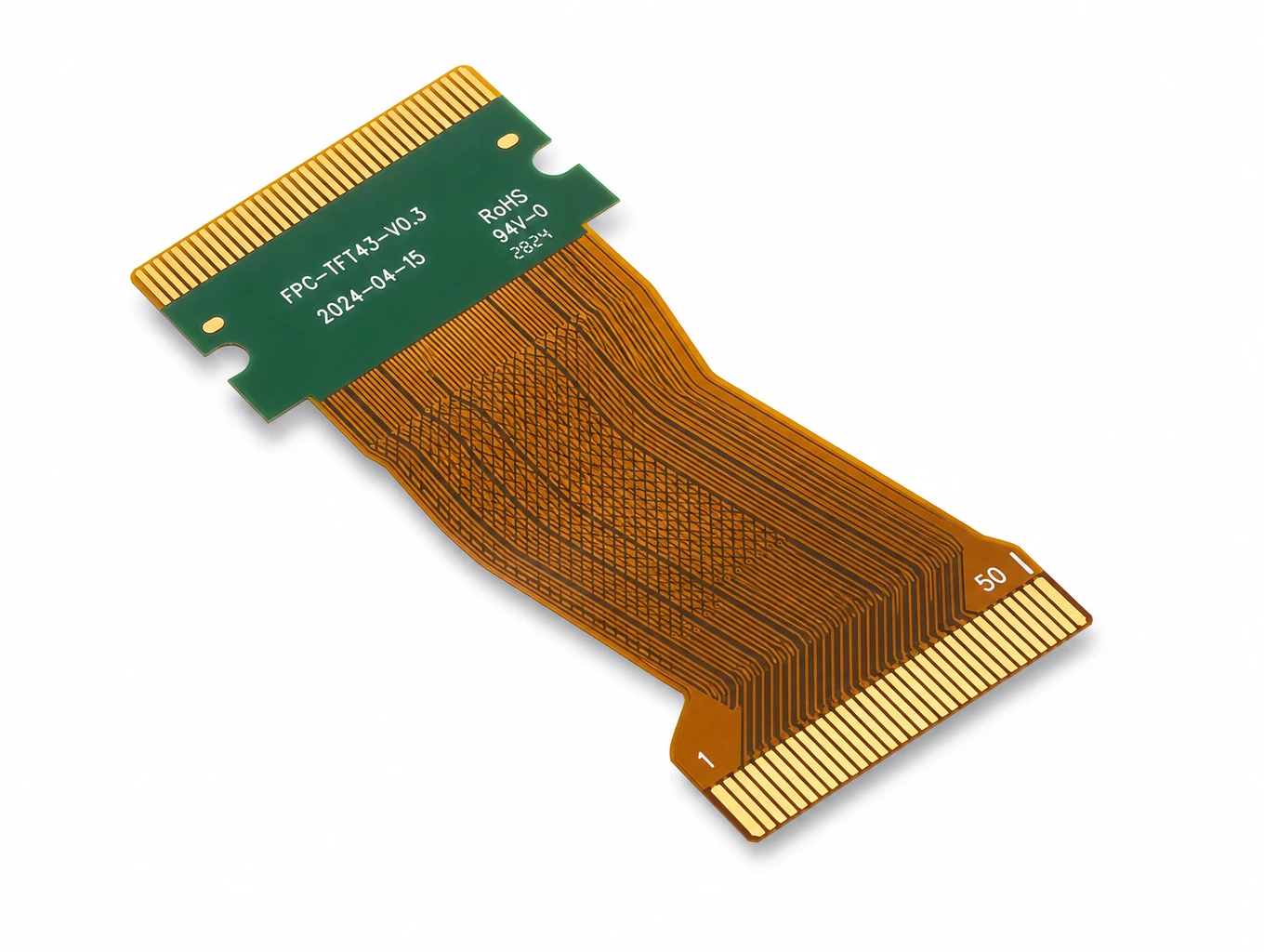
Industrial HMI & TFT-LCD Module FPC
Model: TLX-DFPC-IND05
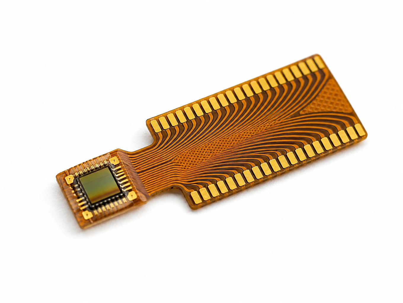
Medical Endoscope Micro-Display FPC
Model: TLX-DFPC-MED06
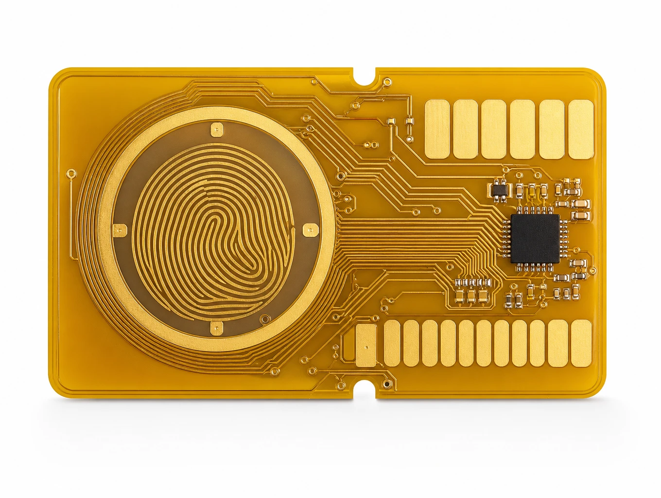
Biometric Smart Payment Card Fingerprint Sensor FPC
Model: TLX-CARD-BIO01
Related Solutions

Medical Device FPC Solutions
Custom flexible circuits for diagnostic equipment, patient monitoring and compact medical electronics. Discuss routing, signal paths, materials and prototype acceptance with Teleconix before releasing your OEM design.
Explore Solutions
Consumer Electronics & Smart Card FPC Solutions
Custom flexible circuits for smart cards, TWS earbuds and compact wearables. Align routing, stack-up, component interfaces and prototype acceptance with Teleconix before releasing your OEM design.
Explore Solutions
RF & Communication FPC Solutions
Custom RF flexible PCB and telecom interconnects for antenna modules, wireless terminals and high-speed communication assemblies. Coordinate materials, signal paths, shielding and connector support with Teleconix before prototype release.
Explore Solutions Medical Device FPC Solutions
Custom flexible circuits for diagnostic equipment, patient monitoring and compact medical electronics. Discuss routing, signal paths, materials and prototype acceptance with Teleconix before releasing your OEM design.
Explore Solutions Consumer Electronics & Smart Card FPC Solutions
Custom flexible circuits for smart cards, TWS earbuds and compact wearables. Align routing, stack-up, component interfaces and prototype acceptance with Teleconix before releasing your OEM design.
Explore Solutions RF & Communication FPC Solutions
Custom RF flexible PCB and telecom interconnects for antenna modules, wireless terminals and high-speed communication assemblies. Coordinate materials, signal paths, shielding and connector support with Teleconix before prototype release.
Explore SolutionsFrequently Asked Questions
Conclusion: release one clear and complete RFQ package
A useful flexible PCB RFQ brings circuit data, construction, installed requirements and acceptance into one controlled package. Check the exported files, name the open questions and compare supplier responses against the same baseline. Release the agreed revision only after the responsibilities and deviations are clear.
To prepare your next quotation, discuss your flexible PCB requirements with Teleconix. Share the current drawings, available manufacturing data, quantities and application conditions. The next step is to confirm the requested scope and close the information gaps that would otherwise carry into production.