
Define what the fatigue test must decide
Flex PCB fatigue testing evaluates how a specified flexible circuit behaves under a defined repeated movement. Start with the decision the test must support. A material comparison, an installed prototype review and approval of a production configuration each need a clear boundary. Write that boundary into the test request before choosing equipment or a cycle count.
For an OEM team, the useful result connects a circuit revision, a motion profile and an acceptance rule. A report that only states a large number of cycles leaves important questions open. The same circuit can experience different local curvature, tension and contact when its guides, clamps or enclosure change. Record the assembly that the result will cover and the assumptions the team still needs to validate.
Separate recurring operation from installation and maintenance movements in the application description. A display tail may flex when the housing opens for service. A robotic sensor connection may change shape on every motion. These operating histories lead to different test objectives. Use the static and dynamic bend guide to establish the mechanical description before developing the endurance plan.
Give the test a named release decision
State who will review the results and what that reviewer may approve. The decision might release a prototype for further integration, accept one construction for a defined duty or identify the next design revision. Assign responsibility for mechanical observations, electrical records and any remaining product qualification. This gives engineering, quality and purchasing a common interpretation of the test.
Describe the full motion and cycle definition
A test specification needs enough information for another laboratory to reproduce the movement. Provide the installed route, the moving and fixed interfaces, the available loop length and the full travel. Identify the drawing convention used for the bend radius. Include photographs or model views at the beginning, middle and end of travel so the fixture designer can see where curvature changes.
Define one counted cycle in plain language. For example, a project may count travel from the home position to the opposite stop and back as one cycle. Record the direction, sequence, dwell and movement profile that accompany that definition. If the equipment counter increments at each reversal, document the conversion in the report. A shared cycle definition prevents otherwise plausible results from being compared on different bases.
Describe the actual use sequence, including low-frequency service events and any combinations of bending, twisting or sliding contact. Identify the speed range and whether the device pauses at a position that holds the flex under strain. The specification should also record permitted assembly variation, such as clamp placement or connector position. Decide which boundary conditions need dedicated samples.
Keep comparison conditions visible
The published IPC-TM-650 Method 2.4.3.1 Revision C describes a particular flexural fatigue and ductility method with a defined specimen and apparatus. If a contract uses this or another method, identify its revision and any agreed deviations. Application-specific motion testing also needs its own documented geometry and endpoint. Compare results only after checking those conditions.
A motion worksheet can describe each operating mode on a separate row. Give the mode a name, list its starting and ending positions, and identify the corresponding controller program. Record how often that mode occurs in normal use and which other movements may follow it. Ask the product team to approve the sequence used for the prototype. Where the use profile remains uncertain, label the assumption and state how the project will obtain better information before making a service-life decision.
Release representative specimens and a sample plan
Identify the complete construction that each sample represents. Record the drawing revision, layer stack-up, finished thickness, copper grade and thickness, protective layers, local stiffeners and surface finishes. Include relevant assembly operations and any approved substitutions. Trace each specimen to its build or material lot so a later investigation can connect a failure to the released configuration.
A test coupon can answer a focused material or process question. An actual circuit can include branches, transitions and mounting features that a simple strip omits. Decide which features the specimen needs to represent for the stated release decision. If a coupon supports only one part of the argument, name the further installed-circuit checks in the plan. Preserve the coupon drawing alongside the result.
Choose the number of samples with the responsible quality or reliability team. The plan should explain the intended comparison, the required confidence where applicable, the available manufacturing variation and the treatment of early failures. Assign samples across relevant lots or builds when those differences form part of the question. Keep identification and allocation clear before the first test starts.
Document the complete flex region
Copper selection belongs in that specimen record. JX Advanced Metals publishes HA and HA-V2 copper foil information with material-specific evaluation context. Use supplier data within its stated construction and test conditions. For the finished circuit, review the copper selection and verification inputs together with the protective layers, geometry and manufacturing route.
Build a fixture that reproduces the installed route
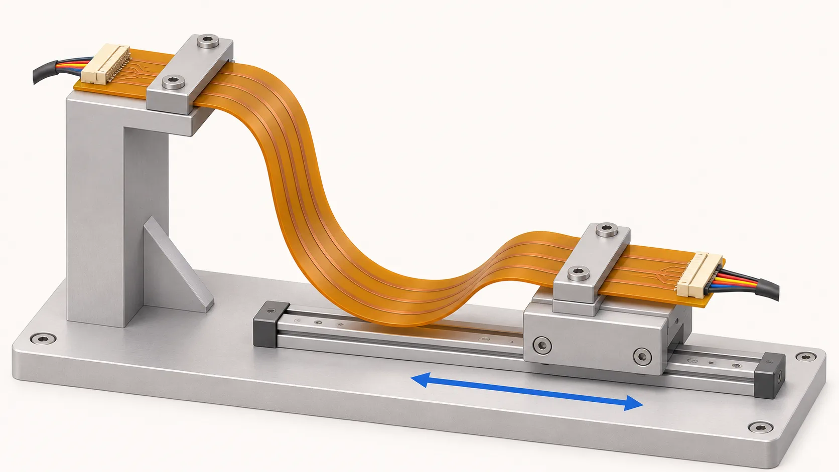
The fixture should establish the supports and free movement needed by the test objective. Locate the moving and fixed interfaces from the controlled drawing. Record the clamped length, contact surfaces, guide positions and cable exits. Keep the connector and measurement leads supported so their movement can be distinguished from the motion applied to the flex region.
Before running an endurance sequence, move an identified sample slowly through the complete stroke. Observe both sides of the circuit where practical. Look for unwanted contact, sliding, local buckling, a changing loop shape or a bend moving into a stiffener transition. Photograph the boundary positions and check that the intended motion repeats. Resolve fixture interference before interpreting an endurance result.
Approve the setup before the counted run
Use a setup checklist that covers specimen orientation, reference marks, clamp settings, alignment and the movement limits. Record any adjustment needed to load the sample. When multiple stations run in parallel, verify the setup on each station and identify its channel in the data. Keep fixture photographs and a revision identifier with the test program.
A setup change can alter the question being tested. If the laboratory moves a guide or changes support after an early failure, preserve the original record and treat the revised setup as an identifiable configuration. The reviewer then has enough information to decide which results can be compared and which need a separate assessment.
Monitor electrical behavior during the movement
Define the electrical observation that will identify a failure. Specify the monitored nets, their accessible endpoints and the required measurement path. Agree on the threshold, measurement range, acquisition interval and any interruption duration that triggers an event. These settings should reflect the circuit function and the question the test must resolve.
A reading taken only after the motion stops describes that measurement condition. If the concern is an intermittent interruption during travel, plan the monitoring and event capture needed to observe it. Establish how the motion counter, electrical channel and time record relate to one another. Save the relevant raw data so a reviewer can examine an event rather than relying only on a pass indicator.
Measurement leads and contacts also need a controlled setup. Secure their route, identify connection points and perform appropriate checks before the run. For measurements where lead resistance matters, Keysight explains four-wire resistance measurement. Select the method and instrument settings with the test provider, including the range, excitation and resolution appropriate to the circuit.
Keep the electrical test boundary clear
Document whether the test monitors a continuity chain, individual nets, an assembled function or another agreed characteristic. Different observations answer different questions. The bare-circuit electrical acceptance guide covers netlist and connectivity records that can support the starting condition. Define any required isolation, signal or functional checks separately in the fatigue plan, with their measurement stage and acceptance criteria.
Run an initial recording at the planned movement settings and check that the saved file contains the expected channels and timestamps. Verify the event-recording arrangement using an appropriate controlled check agreed with the laboratory. Document how the instrument distinguishes an interruption from an operator disconnect or a station fault. Identify which data files require retention and ensure that the sample number appears in their names or accompanying index. Review these records before committing the remaining specimens to a long run.
Agree on exposures, inspections and stop rules
State the environmental conditions for the run and the specimen's preparation history. Depending on the application, the review may need to consider temperature, humidity, cleaning exposure, storage or assembly heat. Choose the conditions with the product team and record the sequence. A combined exposure and motion test needs a clear rationale for how that sequence relates to the intended use.
Set inspection points before the test starts. Decide whether inspections require stopping the motion, unloading a sample or using a reference position. Identify the visual features the reviewer will examine and the electrical checks performed at each interval. Describe how an interruption or inspection affects the recorded cycle count so every specimen has a traceable test history.
Define stop rules for electrical events, visible damage, fixture problems and completion of the target. Assign the person who can authorize a restart. Preserve the first event, relevant data and the specimen's condition before making adjustments. If a contact or instrument problem is suspected, the report should retain that evidence and the reason for the diagnosis.
Record planned and unplanned interruptions
Log power loss, an open enclosure, a station reset, maintenance and changes to measurement connections. Include the counter and time at interruption, the checks performed and the restart decision. Maintain the same sample identifier throughout. These entries help the reviewer interpret whether a run continued under the original conditions or became a different test.
Set expectations for practical issues such as unattended operation and sample storage between sessions. Agree who receives a stop notification and how samples will be handled before examination. Preparing these steps early gives the laboratory a clear response when an unexpected event occurs.
Investigate failures and report surviving samples
A useful failure record starts with the first observed event and its location in the test sequence. Keep the motion count, electrical trace, station identifier and available images together. Mark the specimen orientation and preserve the setup long enough to document the condition. Avoid handling that could erase the feature the investigation needs to examine.
Review the circuit and the measurement system together. Check whether the event follows a bend location, a clamped edge, a transition, a connector or a measurement lead. Use the agreed examination methods to investigate the observation. If the team cannot assign a cause, record the remaining uncertainty and what further evidence would resolve it.
Report samples that reached the planned target with their individual results. Distinguish a sample stopped at the target from one that failed at a recorded count. Keep interrupted or excluded samples visible with the reason for their status. If the review includes a statistical interpretation, have the responsible specialist apply a method appropriate to the sample plan and stopping rules.
Compare changes using a controlled baseline
Suppose an illustrative sensor connection produces interruptions near a support transition. A follow-up build might change free length, support position or construction. Record exactly what changed and keep the measurement criteria consistent where the comparison requires it. If several factors change together, document the limits on assigning the improvement to a single factor.
Use the findings to update the next prototype objective. The prototype validation workflow connects a defined build, recorded observations and the next release decision. Retain failed specimens or analysis images according to the agreed project retention plan.
Make the report usable for the next release
The final report should let an engineer outside the test reconstruct the setup and understand the decision. Include the approved plan, deviations, sample identities, fixture revision, motion definition and measurement settings. Connect summarized results to the underlying records. A purchasing team can then compare the delivered evidence with the scope quoted before the build.
| Report item | What the reviewer needs |
|---|---|
| Released construction | Drawing, stack-up, material and assembly revisions |
| Mechanical conditions | Fixture, support positions, free length, travel and cycle definition |
| Electrical observation | Monitored nets, method, thresholds, event capture and raw data reference |
| Individual results | Target reached, failure count, interruptions and investigation status |
| Release decision | Approved configuration, open items and responsible reviewer |
List the changes that require review before repeating an order. Examples may include a different copper grade, a protective-layer change, revised stiffeners, new contact locations or an altered enclosure route. The engineering team should assess whether existing evidence still applies and which additional checks the revised configuration needs.
Include acceptance records in the RFQ
Send the test plan and requested deliverables with the controlled fabrication package. State who supplies the fixture, who performs the test, how deviations are approved and which data accompanies delivery. Ask for exclusions and unresolved assumptions in the quotation. This makes the review of cost and schedule more specific.
For a moving sensor or industrial interface, the industrial and robotics FPC solutions provide a relevant starting point for the application discussion. Agree the actual construction and verification scope with Teleconix during the project review.
Give every open item a named owner and an evidence requirement. A design engineer may need to approve the installed route, while quality reviews sample allocation and purchasing confirms the requested deliverables. Record the configuration accepted at the review and the next action for any unresolved issue. Keep the released report with the relevant drawing and test files so a later order or design change can be evaluated against the same baseline.
Related Products
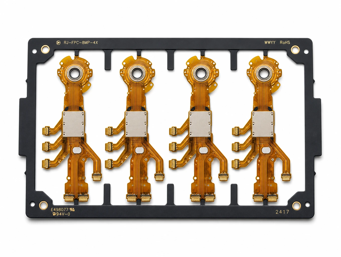
Multi-Branch Humanoid Robotic Joint FPC
Model: TLX-ROB-JNT01
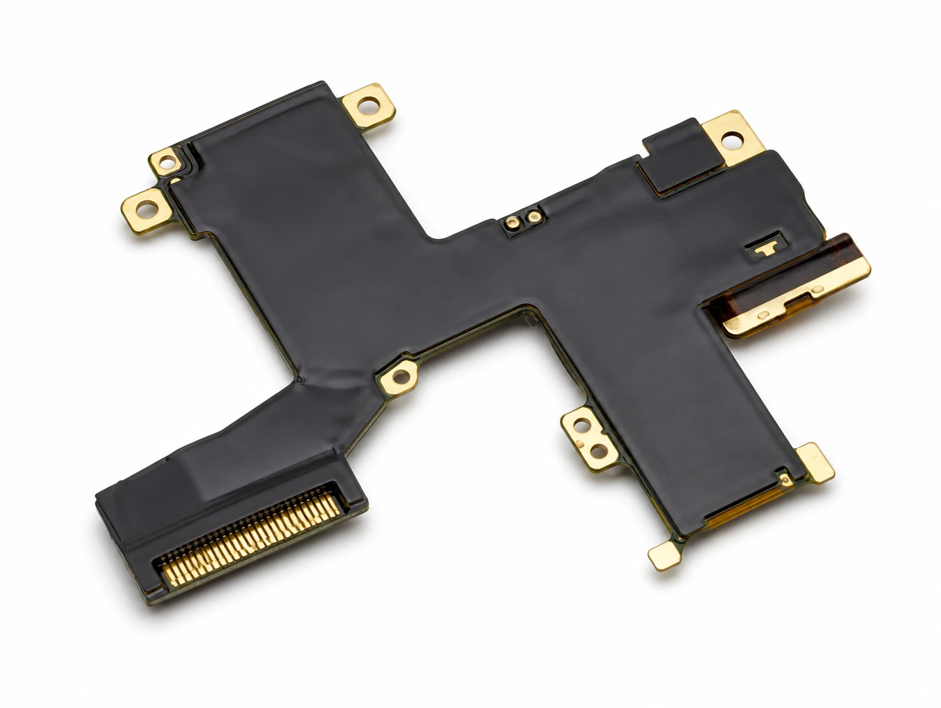
Micro-Form Factor Haptic Surgical Robotics Flex Circuit
Model: TLX-ROB-MED05
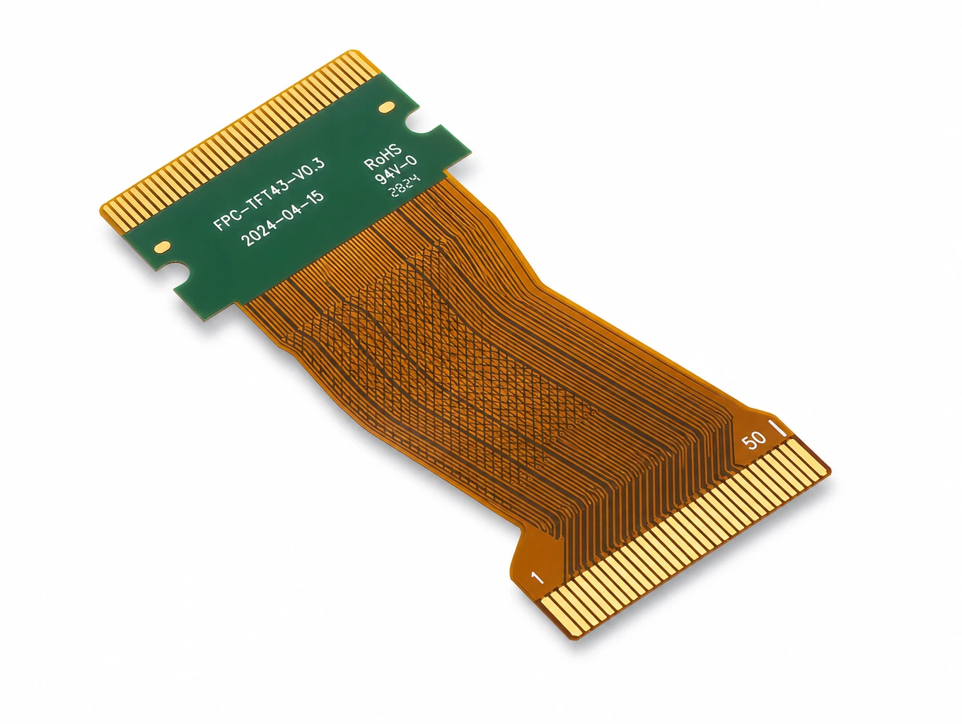
Industrial HMI & TFT-LCD Module FPC
Model: TLX-DFPC-IND05
Related Solutions

AI & Robotics & Special Industrial FPC
Flexible circuits for robotic joints, vision sensors, actuators and industrial interfaces. Match the circuit route to the motion, electrical connections and enclosure of your machine.
Explore Solutions
Display FPC
Display FPC products for OLED, AMOLED, micro-LED and TFT-LCD modules in handheld, wearable, automotive and industrial devices. Review the display interface, connector and installed flex shape together.
Explore Solutions
Smart Automotive Electronics FPC
Automotive FPC products for battery monitoring, ADAS cameras, radar, cockpit displays, steering controls and LED lighting. Select a starting configuration by module function and installation needs.
Explore Solutions AI & Robotics & Special Industrial FPC
Flexible circuits for robotic joints, vision sensors, actuators and industrial interfaces. Match the circuit route to the motion, electrical connections and enclosure of your machine.
Explore Solutions Display FPC
Display FPC products for OLED, AMOLED, micro-LED and TFT-LCD modules in handheld, wearable, automotive and industrial devices. Review the display interface, connector and installed flex shape together.
Explore Solutions Smart Automotive Electronics FPC
Automotive FPC products for battery monitoring, ADAS cameras, radar, cockpit displays, steering controls and LED lighting. Select a starting configuration by module function and installation needs.
Explore SolutionsFrequently Asked Questions
Prepare a traceable fatigue test package
A useful flex PCB fatigue testing program connects the intended movement to an identifiable circuit, a controlled fixture and an agreed failure rule. Document the complete route, define the counted cycle, select representative specimens and plan the electrical observation before the run. Preserve individual results and the reasons for interruptions so the final decision can be reviewed.
Prepare the drawing revision, stack-up, installed motion views, sample plan and requested report fields. Share them through the Teleconix OEM project review to discuss construction, test responsibilities and the evidence required for your next prototype release.