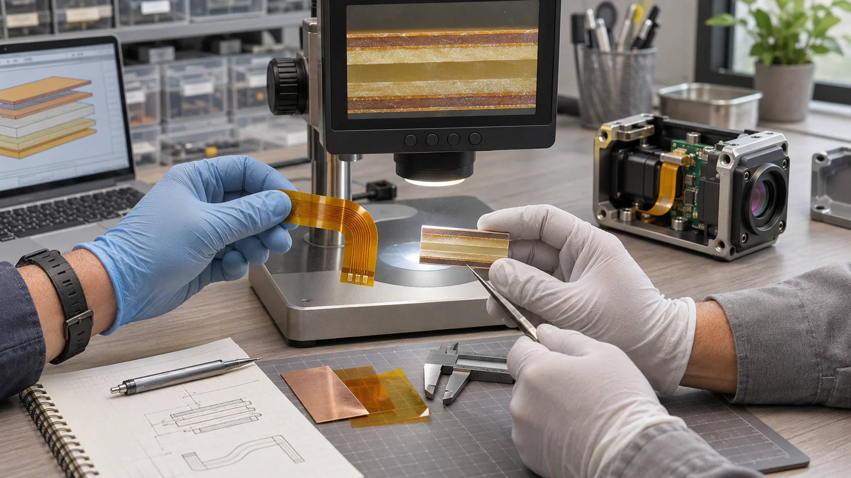


Rolled annealed copper flex PCB: start with the duty
A rolled annealed copper flex PCB uses rolled and annealed copper foil as part of its flexible laminate. RA copper is a candidate when the circuit must accommodate bending or movement, but the foil label does not establish the life of a finished assembly. Choose the actual laminate grade against its route, stack-up and verification requirements.
For an OEM buyer, the useful question is what must happen after the circuit leaves the flat manufacturing panel. A display tail installed once inside a housing has a different duty from a sensor link that moves whenever a mechanism operates. Both are flexible circuits, yet their qualification questions are different.
This guide compares RA and electrodeposited, or ED, copper through that purchasing decision. It connects material identification with mechanical layout, electrical needs, prototype evidence and change control. Use the broader flexible PCB materials guide when reviewing the dielectric, coverlay and reinforcement around the conductor.
- Identify the proposed foil and laminate grade rather than accepting a generic copper label.
- Separate a fixed installation bend from repeated operating motion.
- Evaluate the finished circuit, including its supports and assembly history.
- Agree on evidence and substitution rules before releasing production.
A drawing that says only “RA copper required” still leaves substantial room for assumptions. Copper thickness, dielectric construction, coverlay and the permitted manufacturing build-up remain relevant. The goal is an agreed, traceable construction that can be compared with the application, rather than a material name added to an otherwise incomplete request.
Compare RA and ED copper at the grade level
RA and ED describe different foil manufacturing routes. They do not divide every available product into one reliable class and one unsuitable class. Ask the laminate supplier to identify the specific foil option and supporting data, then compare candidates under conditions relevant to the intended circuit.
As one material-specific example, JX Advanced Metals describes its HA and HA-V2 rolled foils as engineered for flexibility through controlled grain structure and orientation. Those statements apply to the named products and their published evaluations; they are not a lifetime specification for an arbitrary FPC made with RA copper.
ED options also exist for flexible circuitry. Sheldahl lists high-ductility ED copper among the foil choices for its adhesive-based copper laminates. That is a practical reason to reject a blanket statement that all ED copper is inappropriate for flex. It does not establish that a particular ED grade will meet a particular repeated-motion duty.
Read the full material designation
A family name may cover several copper constructions. The Pyralux AP data sheet identifies different copper options using product-code suffixes. Check the current supplier document for the exact ordered code; do not assume a code rule from one family applies to every manufacturer.
Request a proposed material callout containing the laminate manufacturer and grade, copper type and starting thickness, dielectric thickness and applicable drawing revision. Where an equivalent is offered, ask for its full identification and the differences requiring review. A certificate showing only a broad material family may not resolve these details.
Separate fixed bends, service handling and repeated motion
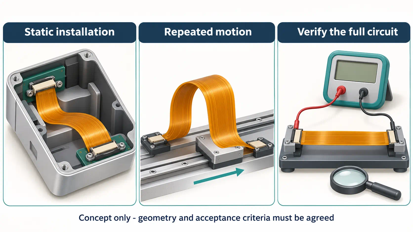
Classify the movement before comparing foil performance. A static installation bend remains in its intended shape during normal use. Service handling may introduce occasional additional bends. A dynamic application moves repeatedly in operation and needs an explicitly defined motion envelope and test plan.
Describe the installed path with enclosure views or a mechanical model. Mark where the flex is held, where it moves and whether it can contact neighboring parts. Include travel limits, changes in bend direction and any torsion. A flexible tail that looks relaxed in a flat drawing can be pinched after a cover is fitted.
For repeated motion, state the operating duty, environment and required service life as system requirements. The circuit supplier can then discuss a candidate construction and representative evaluation. Do not replace that discussion with an unspecified claim such as “high-flex copper” or a cycle value copied from a different material coupon.
Keep handling events in the review
Assembly can impose bends that differ from the operating route. Explain how the flex passes through the housing, how connectors are inserted and whether technicians may remove the assembly. A circuit intended to remain static can still be damaged by an uncontrolled installation fold. Define a supported installation sequence where the route is sensitive.
The flex PCB bend-radius guide develops this geometry review. The robotics motion and sensor guide provides an application context for moving links. Neither a material label nor a general bend guideline replaces verification of the released circuit in its actual arrangement.
Use the illustration below to distinguish the review questions. It is a conceptual explanation, not a drawing from which to manufacture a fixture or assign an allowable bend radius.
Evaluate copper within the finished stack-up
Copper bends as part of a composite circuit. Dielectric films, adhesives, coverlay, other copper layers and local reinforcement affect how that composite behaves. Compare complete proposed constructions, particularly in the area that moves, before attributing a difference solely to RA or ED foil.
Document the finished flexible-region layer sequence and thickness assumptions. Distinguish starting foil from any additional copper deposited during fabrication. Ask which regions receive that build-up and how the final conductor construction is controlled. A starting-foil number on the purchasing specification may not describe every finished section.
Review how the bend region transitions to pads, connector fingers and supported areas. Keep abrupt geometry changes, unnecessary features and local stiffness changes under engineering review. Connector attachment, coverlay openings and stiffener edges can create constraints that remain important after a foil upgrade.
Specify laminate and coverlay independently
An adhesiveless base laminate does not itself identify the foil type, and it does not mean the finished FPC contains no adhesives. Use the adhesiveless stack-up selection guide to separate the core choice from coverlay and reinforcement. Preserve those distinctions in the drawing and in supplier quotations.
For a multilayer construction, show which layers continue through the flexible span and where bonding or reinforcement changes. Ask the supplier to review whether the proposed architecture suits the movement before committing to panel tooling. Avoid carrying a construction from a static multilayer assembly into a dynamic link without a new assessment.
Evaluate the assembled route with its connector supports and housing features present. A successful material coupon test can support selection, but it cannot show that the final enclosure provides enough clearance or that a stiffener edge stays outside the moving region.
Balance mechanical needs with electrical and process requirements
A foil decision must also satisfy the electrical circuit and the intended manufacturing process. Review conductor geometry, current and temperature requirements, signal behavior and assembly exposure together. A material chosen for bending still needs to support the actual interface and accepted fabrication route.
For a power path, provide operating and transient current assumptions along with the thermal environment and allowed temperature rise. Let the design review resolve conductor dimensions and the complete construction. Simply requesting thinner copper to improve flexibility can conflict with other requirements if the electrical path is not reconsidered.
For high-speed or RF links, review copper surface characteristics together with dielectric properties, line geometry, reference conductors and transitions. RA versus ED alone does not establish channel performance. Ask for the material information and electrical analysis relevant to the proposed interface; avoid declaring one foil family universally lower loss.
Include the assembly condition in qualification
State whether the FPC will be supplied bare or assembled, which regions carry components and what thermal or attachment processes are anticipated. The evaluated specimen should represent the released processing state when that state affects the decision. Record any difference between a bare coupon and the intended finished assembly.
If impedance is controlled, connect the material proposal with the layer geometry and agreed verification described in the controlled impedance planning guide. Mechanical and electrical checks answer different questions. Passing a continuity test after bending does not by itself verify signal integrity over the operating interface.
When requirements conflict, make the tradeoff explicit. The solution may involve a different route, stack-up or support arrangement rather than changing only the copper label. Record the accepted compromise so a later purchaser does not unintentionally remove a necessary design constraint.
Turn supplier test data into a representative verification plan
Supplier data is most useful when its specimen and test conditions are understood. Compare the material, copper thickness, circuit construction, movement and failure definition with the intended application. A result from another configuration supports discussion; it is not an automatic production guarantee.
Ask what was tested: loose foil, copper-clad laminate, a patterned coupon or a finished circuit. Record support spacing, bend geometry, travel, loading direction and environment. Also identify whether the reported value describes a typical result, a specification limit or a qualification outcome for a named construction.
Define acceptance before testing starts. Depending on the application, evidence may include inspection, continuity or resistance monitoring, mechanical fit and operation of the relevant interface. Intermittent connections can require monitoring during movement rather than only a measurement before and after the test.
Use a review matrix instead of an unsupported cycle claim
| Review item | Information to agree | Record to retain |
|---|---|---|
| Construction | Foil grade, finished layers, thicknesses and processing state | Approved stack-up and build revision |
| Geometry | Supports, bend envelope, travel and orientation | Fixture or installed-route definition |
| Duty and environment | Application-derived movement and exposure conditions | Approved test procedure |
| Acceptance | Electrical and visual limits, sampling and stop conditions | Results, deviations and disposition |
Use the OEM prototype validation guide to connect these checks with the build package. Preserve specimen identity and any deviations from the proposed production design. If the route or material later changes, review which evidence still applies instead of carrying forward the original approval without examination.
Write a copper callout that suppliers can quote consistently
A useful RFQ connects the copper requirement to a controlled design package. State the requested construction, the intended duty and the evidence needed for approval. Ask suppliers to identify assumptions and exceptions so quotations can be compared on the same scope.
Include circuit artwork, outline, layer map and stack-up revision; the laminate and foil proposal; coverlay and reinforcement details; and connector or assembly drawings. Mark the movement region on a mechanical view. Provide quantities and the division of responsibilities for prototype evaluation, assembly and final acceptance.
A practical callout can require the supplier to declare the laminate manufacturer and complete grade, copper type, starting thickness, relevant finished build-up and material traceability. Where the OEM has not selected a grade, request a proposal against documented application requirements. Do not invent a material code to make an RFQ look complete.
Define how alternatives are approved
Ask whether an alternative changes foil type, treatment, dielectric thickness or assembly assumptions. Record approval before that material is substituted. A generic “equivalent material allowed” statement can undermine the very copper selection that qualification was intended to control.
For comparison, separate material availability, fabrication scope, test scope and commercial assumptions. Do not assume RA always creates a fixed price premium or that an ED option always improves delivery. The actual offer depends on the identified material, construction, quantity and supplier arrangements.
Keep unresolved points visible in the quotation review. A shorter commercial response is not necessarily a more complete technical offer. Resolve the missing construction and verification details before treating two prices as directly comparable, and retain the accepted supplier proposal with the released circuit data.
Release the decision with traceability and change control
Approve the complete material and circuit configuration, not just the words “RA copper.” Tie the decision to the released drawing, accepted supplier proposal and relevant verification records. This gives purchasing and manufacturing a common definition of what was evaluated.
For incoming documentation, agree on the identification needed to connect the delivered material or circuit lot with the approved construction. The required record depth should follow the application and purchasing agreement. Avoid demanding unrelated certificates that do not identify the actual foil or laminate under discussion.
Before a subsequent build, check whether the laminate grade, foil option, fabrication build-up, outline, support arrangement or assembly process has changed. Some changes may be straightforward; others can affect the interpretation of previous results. Assign a technical owner to decide what review or retesting is appropriate.
Keep failures specific. If a prototype shows a crack, intermittent connection or poor fit, document its location and test condition before selecting a different foil. A new copper grade cannot correct every cause of damage. The mechanism may also involve routing, handling, support, processing or a local feature.
Consider a hypothetical display module installed once in an instrument. Its review may concentrate on the insertion sequence, supported connector thickness and clearance after closure. A moving inspection head needs a different review of travel, repeated bending and electrical behavior during motion. Even if both proposals use RA copper, approving the first assembly does not approve the second. Keep the application assumptions attached to each part number rather than reusing a generic material approval.
Where a drawing permits more than one construction, identify which variants were evaluated and which still require review. Keep samples or inspection records identifiable to the actual build. This makes later troubleshooting more useful than a purchase history containing only the shorthand term “flex copper.”
Teleconix can use your documented application and manufacturing files as the starting point for a project discussion. The relevant product and solution examples below provide application context; they do not imply that every listed product shares one foil grade or has passed the verification plan proposed here.
Related Products
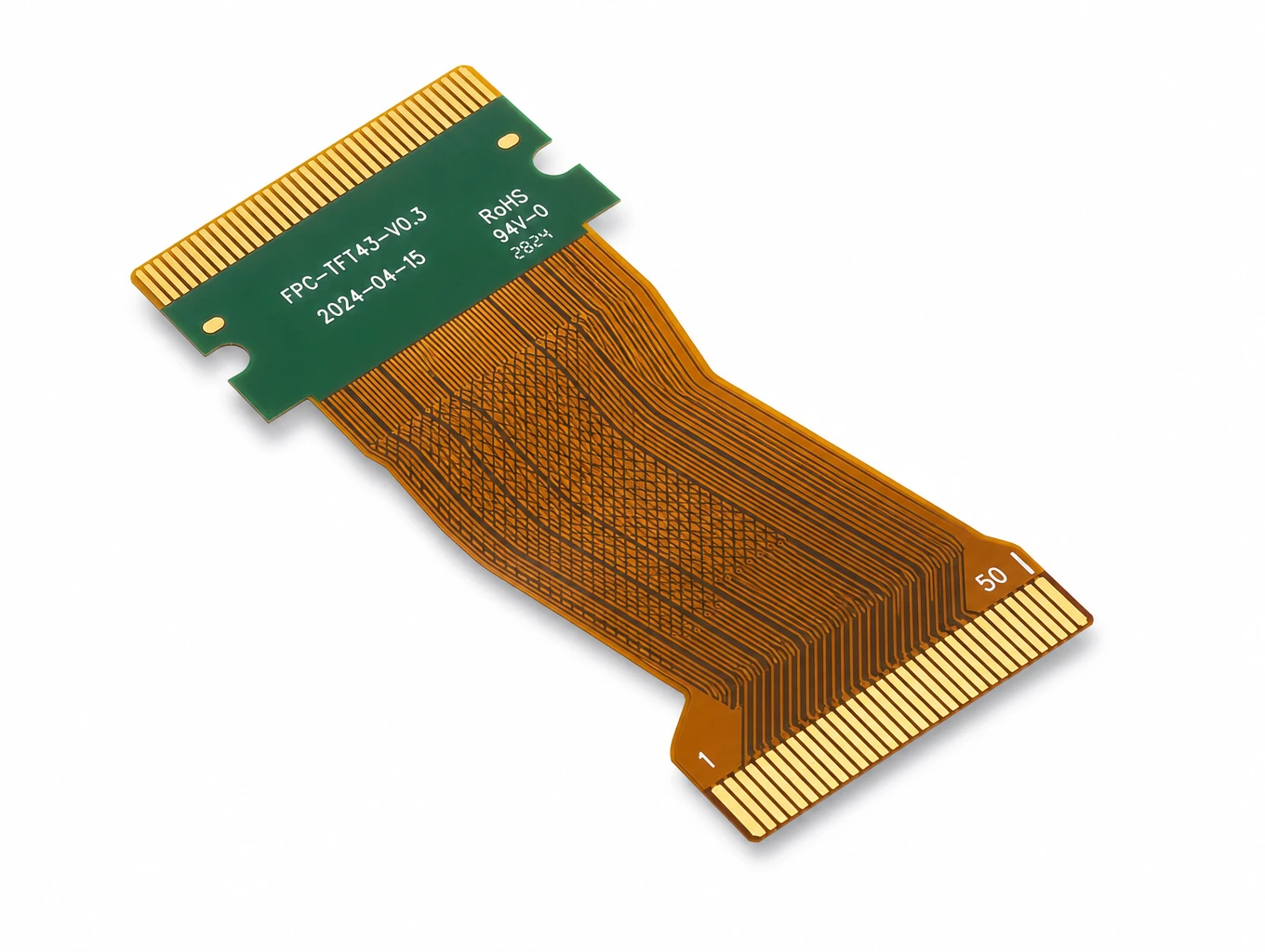
Industrial HMI & TFT-LCD Module FPC
Model: TLX-DFPC-IND05
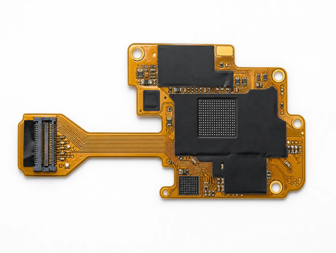
High-Speed ADAS Multi-Camera SerDes FPC
Model: TLX-AUTO-ADAS02
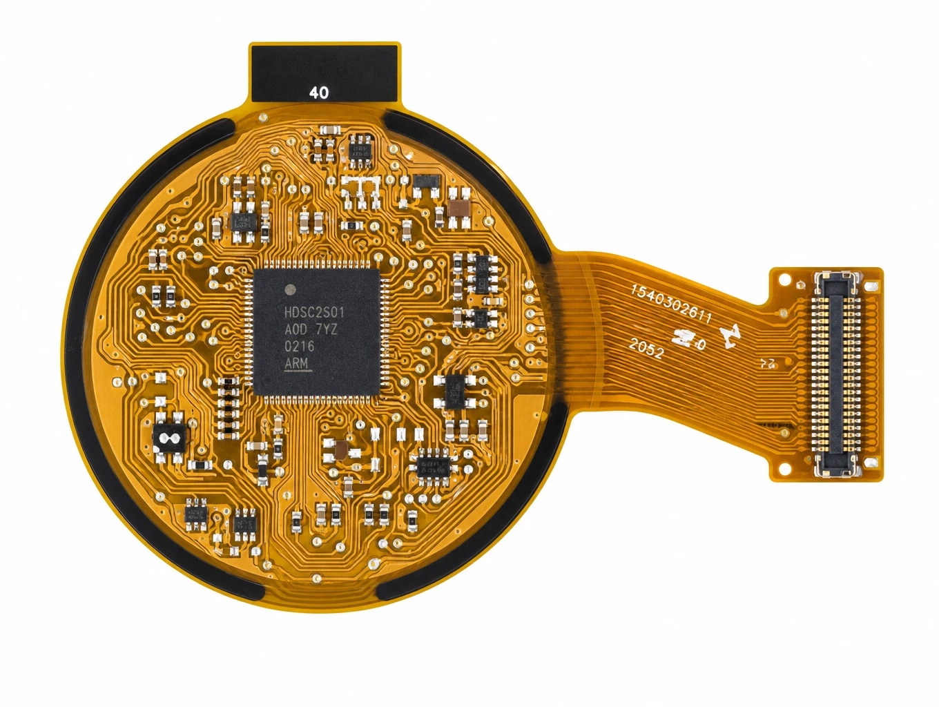
Wearable Smartwatch & Round AMOLED FPC
Model: TLX-DFPC-WEAR04
Related Solutions

Display FPC
Display FPC products for OLED, AMOLED, micro-LED and TFT-LCD modules in handheld, wearable, automotive and industrial devices. Review the display interface, connector and installed flex shape together.
Explore Solutions
AI & Robotics & Special Industrial FPC
Flexible circuits for robotic joints, vision sensors, actuators and industrial interfaces. Match the circuit route to the motion, electrical connections and enclosure of your machine.
Explore Solutions
Consumer Electronics & Smart Card FPC Solutions
Custom flexible circuits for smart cards, TWS earbuds and compact wearables. Align routing, stack-up, component interfaces and prototype acceptance with Teleconix before releasing your OEM design.
Explore Solutions Display FPC
Display FPC products for OLED, AMOLED, micro-LED and TFT-LCD modules in handheld, wearable, automotive and industrial devices. Review the display interface, connector and installed flex shape together.
Explore Solutions AI & Robotics & Special Industrial FPC
Flexible circuits for robotic joints, vision sensors, actuators and industrial interfaces. Match the circuit route to the motion, electrical connections and enclosure of your machine.
Explore Solutions Consumer Electronics & Smart Card FPC Solutions
Custom flexible circuits for smart cards, TWS earbuds and compact wearables. Align routing, stack-up, component interfaces and prototype acceptance with Teleconix before releasing your OEM design.
Explore SolutionsFrequently Asked Questions
Choose the foil, then verify the released circuit
A rolled annealed copper flex PCB decision should resolve a defined application requirement. Identify the actual material, compare it with appropriate alternatives and evaluate the complete circuit in its intended route. Keep the accepted construction and the evidence together.
Prepare your current stack-up, mechanical views and motion requirements, then discuss your flex PCB material requirements with Teleconix. Use that review to agree on a material proposal, prototype scope and acceptance records before production release.