
Robotics FPC design starts with the installed system
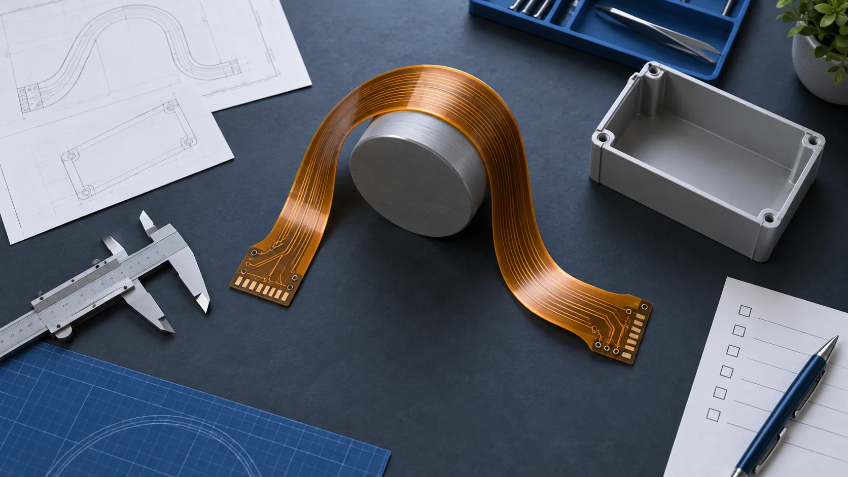
A robotics FPC connects electronics inside a robot while fitting its mechanical route, assembly sequence and operating movement. An encoder connection inside a wrist has different requirements from a stationary sensor tail or a power link near a motor. Define those functions before choosing the circuit outline or requesting a quotation.
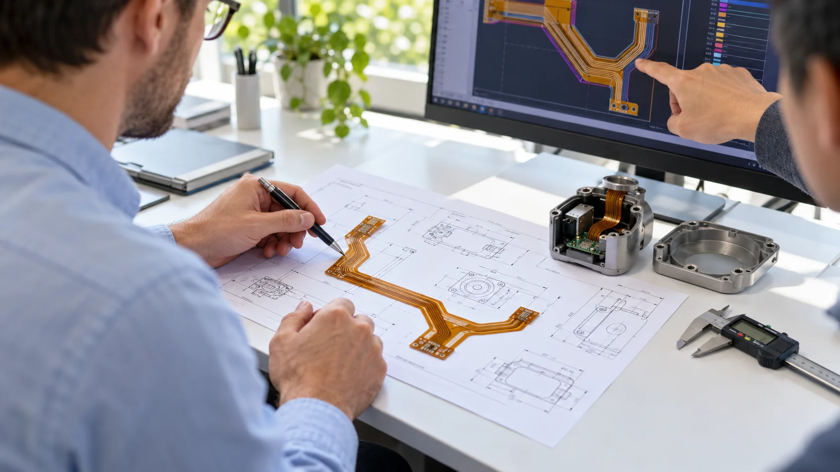
The useful starting point is an interface map: what connects, which parts move, where the circuit is supported and what evidence will demonstrate acceptable operation. A flat circuit drawing alone cannot answer whether a tail rubs against a cover or pulls on a connector at the end of travel.
This OEM guide turns those questions into a practical design and purchasing brief. Review the robotics and industrial FPC products for application examples, then use your own mechanical and electrical documents to define the requested solution. Product examples do not replace a project-specific motion test.
Project review priorities
- Identify which circuit regions remain fixed and which move during operation or service.
- Approve the installed route, connector support and interface documents together before ordering prototypes.
- Define the specimen, motion sequence, operating environment and failure criteria for the acceptance test.
- Keep quotation assumptions and subsequent changes attached to the same controlled project revision.
Separate moving interconnects from stationary sensor tails
Classify every flex region by what it actually does. A circuit folded during installation and then fixed in place is different from a circuit that bends on every machine cycle. Service access can introduce another condition: a nominally stationary tail may move whenever a technician opens the housing.
Altium's rigid-flex design documentation distinguishes static and dynamic use and explains that this affects material selection and construction. Apply that distinction to each region of the robot rather than describing the whole assembly simply as flexible.
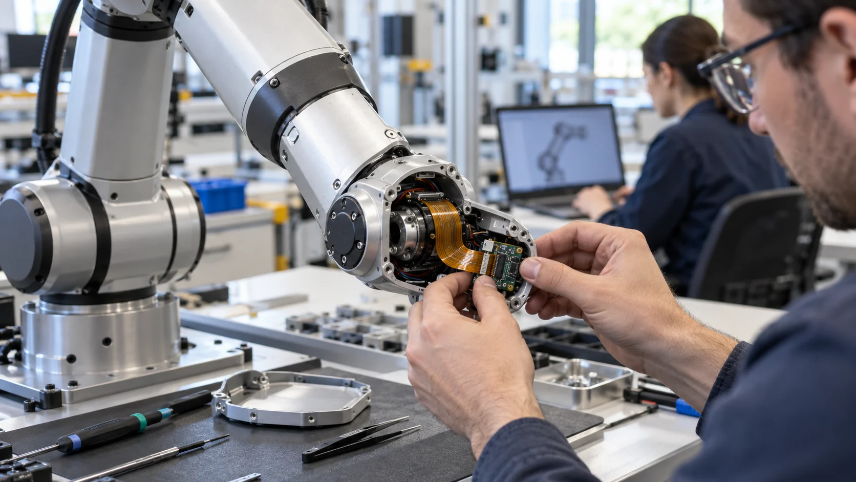
For a robot joint FPC, mark the fixed ends, the intended moving span and any transitions into supported electronics. Identify reciprocal bending, twisting or a combination of movements. If the mechanism rotates continuously, investigate the complete interconnect architecture; do not assume a finite flex loop can accommodate unlimited turns.
Build a motion and interface requirements brief
Give the circuit supplier a brief that links the robot function to measurable requirements. Include the intended duty, the mechanical revision and the interface documents. When a condition is unknown, list an owner and a decision date so that a missing input does not become an unreviewed manufacturing assumption.
| Review area | Input to collect | Decision to close |
|---|---|---|
| Function | Encoder, vision sensor, control, power or combined paths. | Which interface owns each net? |
| Movement | Travel limits, axes, speed profile and repeated sequence. | What is the complete operating route? |
| Supports | Clamps, connector positions, covers and moving obstructions. | Where can strain enter the contacts? |
| Environment | Temperature, vibration, fluids and cleaning exposure. | Which conditions require verification? |
| Acceptance | Electrical checks, motion fixture and failure criteria. | What constitutes an approved prototype? |
Keep normal operation, occasional service movement and abnormal loading separate. State which conditions belong in the approval plan and which are outside the requested scope. A requirement such as reliable in a robot is too broad to guide construction or compare supplier proposals.
The following sections expand this brief into engineering checks. Purchasing can use the same document to compare quotations, while the validation team uses it to confirm that the delivered samples represent the intended configuration. Retain the brief with the released drawing set.
Check the whole swept route, not one attractive pose
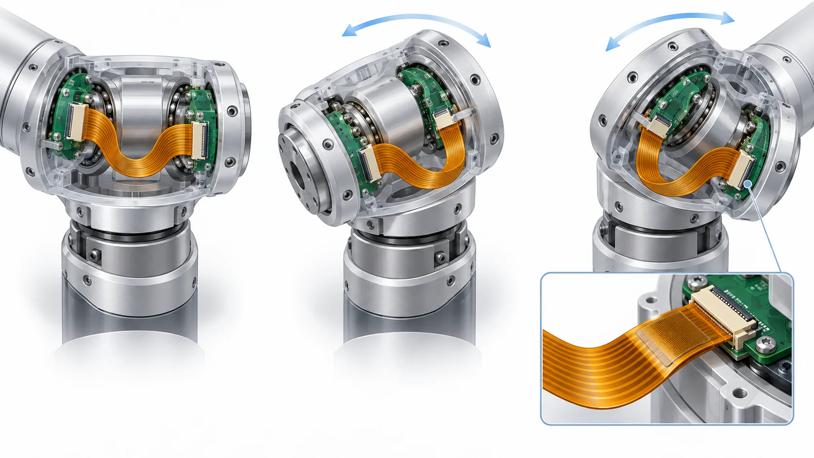
Review the flex route at the travel limits and at intermediate positions where the loop changes shape. Look for rubbing, pinching, reverse folds, local buckling and tension at the ends. Check the effect of nearby brackets, fasteners and covers after the complete mechanism is assembled.
Use an installed mechanical model to describe the route and a physical mockup to expose handling problems. A model can reveal a nominal clearance without demonstrating how the thin circuit actually settles between supports. Record both the intended route and the observed prototype behaviour.
For a robotic arm flexible PCB, include the combined motion of neighbouring axes if it changes the available space. Keep a controlled loop rather than allowing excess length to wander into the mechanism. Use the static and dynamic bend guide for the underlying bend discussion; determine the working geometry from the selected construction and test plan.
Agree a construction for each mechanical region
Specify the proposed stack-up together with the required function of each region. The moving span, supported connector tail and populated sensor area may need different treatment. A material name or total thickness does not describe all the interfaces that affect assembly and movement.
Ask the supplier to identify the conductor material, protective layers, adhesive system and local reinforcement in its proposal. Explain which items are mandatory and which alternatives may be reviewed. Any substitution that affects flexibility or local thickness should return to the mechanical and acceptance review.
Würth Elektronik's Flex Solutions design guide treats dynamic bending as a project-specific construction problem. Use the flexible PCB materials guide to organise the supplier questions. Do not assign a universal lifetime from the words polyimide or rolled annealed copper; the installed design still needs evidence.
Keep connector support outside the moving span
Define the connector interface with the complete part number and mating drawing. Review contact side, exposed contact geometry, finished tail thickness, insertion direction, retention and access to the latch. Similar pitch and conductor count do not establish that a tail will fit or remain correctly seated.
Place the supported tail and any reinforcement so that normal movement does not pull directly on the contacts. Review how the circuit exits the connector and where support ends. A stiffened region can help one interface while creating an abrupt transition elsewhere if its position is not considered.
Use the connector reinforcement checklist when defining local thickness and inspection locations. Test the finished tail in the actual connector, including the enclosure and assembly sequence. Record the approved support method instead of leaving the production operator to decide where to add tape or a clamp.
Define sensor signals before specifying fine routing
Identify the exact sensor, encoder or vision module and its electrical interface before setting layout constraints. Capture the pin map, supply requirements, reference connections and any manufacturer instructions. A connection carrying low-level analogue sensing needs a different review from a digital interface, even inside the same robot.
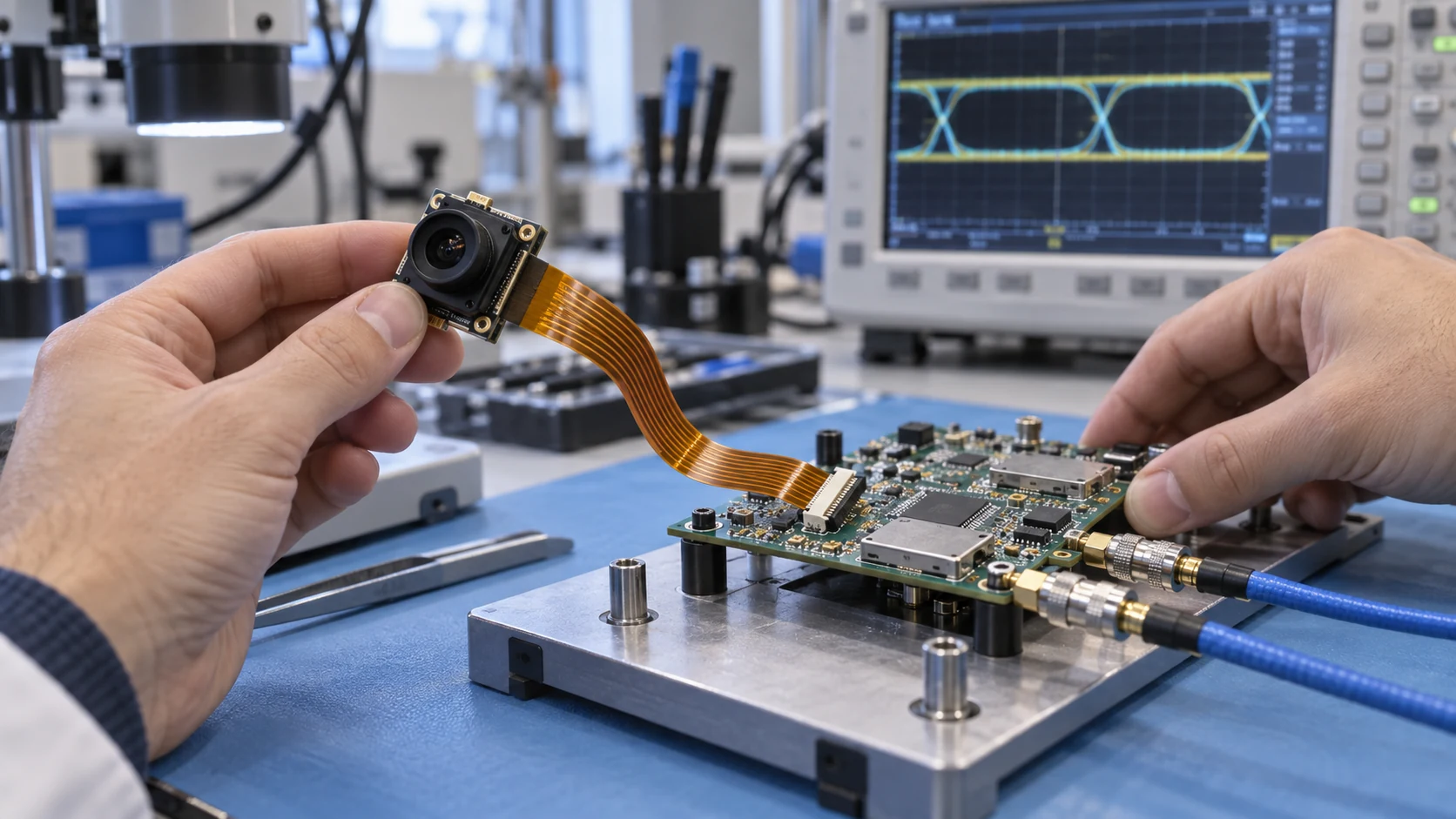
Texas Instruments' motor position encoder interface overview describes several encoder interface types and their EMC challenges. Its examples support checking the selected interface explicitly, not copying one generic encoder pinout or assuming every sensor uses the same signalling.
For a flexible PCB for industrial sensors, document which nets require controlled geometry and who approves the constraints. Use the controlled impedance planning guide when impedance is a real requirement. Connect the circuit specification to the module documents and the system test, rather than adding a high-speed label without acceptance criteria.
Review motor power and sensing paths together
Map the relationship between power paths, control signals and sensitive measurements across the full assembly. Include connectors, return paths and nearby motor electronics. Moving a sensor tail away from one obstruction may bring it closer to another electrical or thermal influence, so coordinate the mechanical and electrical review.
Record the relevant operating states, including startup, acceleration, braking and any other condition identified by the system designer. Ask which state is most demanding for the connection. A successful idle reading does not establish that the sensor path behaves correctly during the intended operating sequence.
If shielding or additional copper is proposed, review the mechanical effects as well as its intended electrical role. Added layers can change the moving construction and local connector fit. Determine conductor and contact requirements from the actual electrical load and thermal conditions; a generic copper weight is not a complete power-path acceptance rule.
Describe the environment the interconnect really sees
Specify conditions at the circuit location rather than relying on a broad industrial label. A flex inside a sealed sensor housing may see a different environment from one near a warm motor or a service opening. Identify temperature, vibration, humidity and any plausible fluid or cleaning exposure.
Separate the enclosure protection from the protection provided by the circuit construction. A coating, coverlay or housing feature does not by itself establish compatibility with every cleaning agent. Ask the responsible designer to define the exposure and the verification evidence needed for the assembled device.
Include storage, transport, soldering and service handling where they affect the selected materials or contacts. Keep these conditions in the controlled requirements set. If the customer later changes the cleaning process or mounting location, review the affected checks before assuming the original prototype approval still covers the new configuration.
Make assembly and service access repeatable
Write the installation sequence before freezing the circuit outline. Identify when the robot is safely isolated, how the boards are supported, how the tail enters the connector and when covers are fitted. Operators need a repeatable method that does not use the circuit as a handle.
Follow the selected connector's handling instructions. For example, Hirose's back-flip FH insertion guidance warns against closing the actuator before FPC insertion because this can increase insertion force. That instruction applies to the specified connector type; check the actual component documentation.
Define inspection access and permitted service operations, including how a technician distinguishes cable ends or revisions. Use the FPC assembly planning guide to connect tooling, handling and responsibility. Review a representative build with the people who will assemble it, not only the engineers who created the model.
Use a prototype to separate fit faults from signal faults
Give the prototype team a sequence that checks identity and fit before powered operation. Verify drawing revision, connector orientation, seating, support and clearance. Record observations with the mechanism open and after enclosure closure, because that final step can change the circuit route or contact loading.
For a sensor dropout, log the robot pose, operating state and exact symptom before replacing parts. Compare one relevant condition at a time. A continuity check can help investigate an open connection, but it cannot establish that firmware settings, interface timing or the complete sensor system are correct.
Preserve photographs and test records that identify the actual sample. Record whether a routing change, connector reseating or support change alters the symptom. Avoid repeatedly bending a suspect circuit without a plan: extra handling can introduce damage and make the original cause harder to distinguish from the investigation itself.
Define motion acceptance before quoting a cycle target
A motion-life target needs a defined specimen, fixture and operating sequence. Document the construction, installed geometry, support points, travel, speed profile and environment. Agree how the test monitors electrical operation and what event counts as failure before samples enter the fixture.
Choose the test duration and sample plan from the product's intended use and engineering requirements. A supplier's successful demonstration on another construction is useful context, but it does not qualify a different robot wrist. A circuit that still looks intact may also require electrical or system checks under motion.
The prototype validation checklist helps organise build and approval records. Include a defined response to an interrupted test or a failed sample. If a result drives a material, support or route change, identify which checks must be repeated and keep the earlier revision's evidence separate from the new approval.
Release an RFQ with clear ownership and revision control
Send the fabrication data together with the installed route and the interface documents that define the design. Add the proposed stack-up, local reinforcement, connector details, quantities and acceptance requirements. If assembly is requested, include the BOM, placement data and assembly drawing as applicable.
Define who supplies the design, who may propose changes and who approves them. Ask the quotation to distinguish fabrication, components, assembly tooling, testing and any customer-supplied items. This prevents two proposals with different scopes from appearing directly comparable simply because they share the same circuit outline.
Retain one release manifest with file names, revisions and unresolved issues. When a motor, sensor, connector or housing changes, assess the consequences for the interconnect as well. Use a signed-off change record to explain what was reviewed, what remains applicable and what needs another prototype check before purchasing the revised build.
Example: turn a robot wrist request into a testable brief
Consider an illustrative request to connect an encoder board inside a compact wrist. The original instruction, make a flexible cable that fits, leaves the interface, motion and acceptance undefined. Replace it with the exact encoder and connector documents, a controlled enclosure model and the required operating positions.
Next, mark the stationary board supports and the intended moving loop. Have the team record the closest clearances through the travel range, the assembly access and the expected service handling. Ask the supplier to explain its proposed construction and any assumptions it needs the customer to approve.
Finally, order prototypes against that revision and agree the fit, electrical and motion checks before testing begins. This is a planning example, not a Teleconix customer case or a measured lifetime result. It shows how an OEM buyer can turn an uncertain request into comparable proposals and evidence that supports a release decision.
Related Robotics and Industrial FPC Products
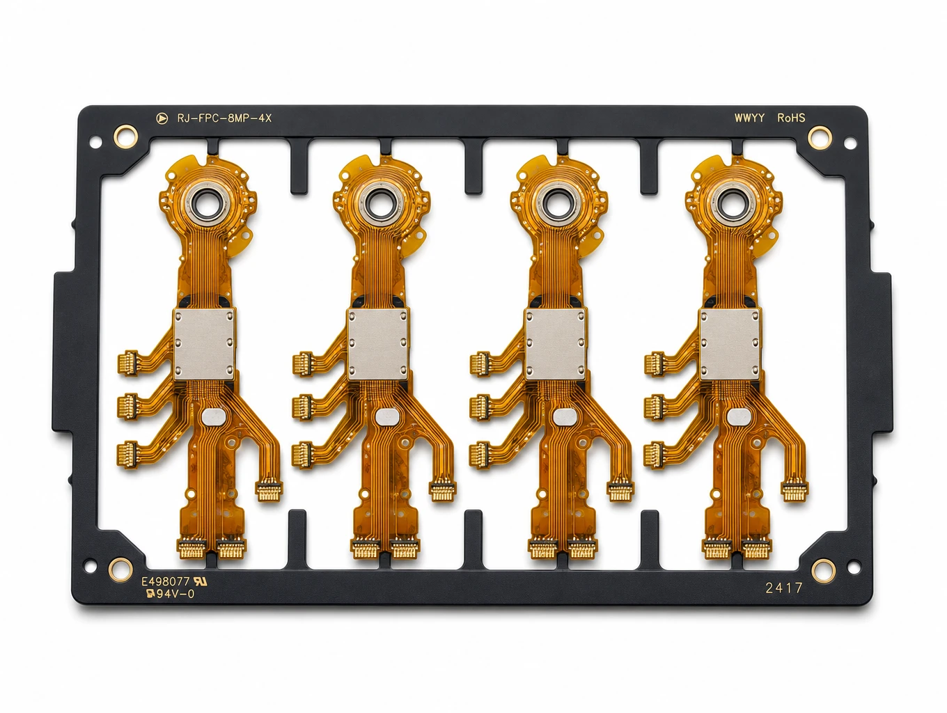
Multi-Branch Humanoid Robotic Joint FPC
Model: TLX-ROB-JNT01
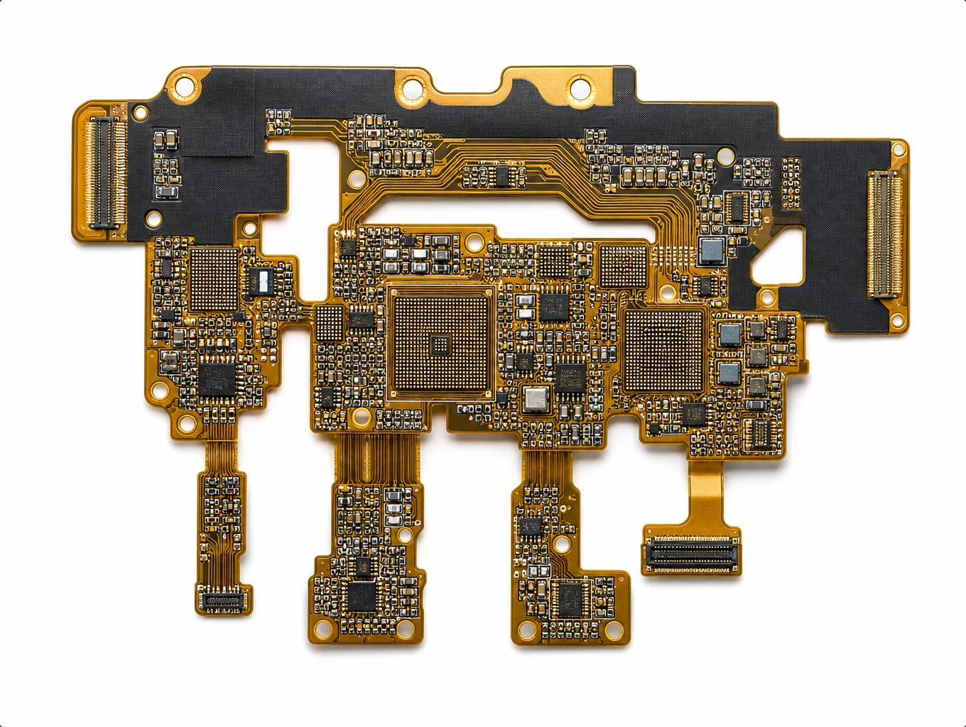
High-Speed AI Vision & LiDAR Sensor Matrix FPC
Model: TLX-AI-VIS02
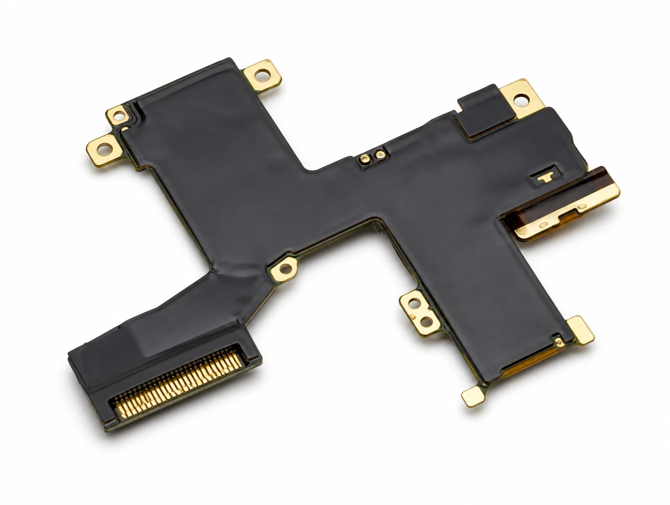
Fully Shielded CNC & Industrial Machine AI Interface FPC
Model: TLX-IND-CNC06
Related FPC Application Solutions

AI & Robotics & Special Industrial FPC
Overcome severe mechanical stress and extreme spatial constraints in your automated hardware. We design and manufacture custom flexible circuits engineered to endure over 2 million continuous bending cycles in multi-axis robotic joints, bionic grippers, and autonomous AGV/AMR platforms.
Explore Solutions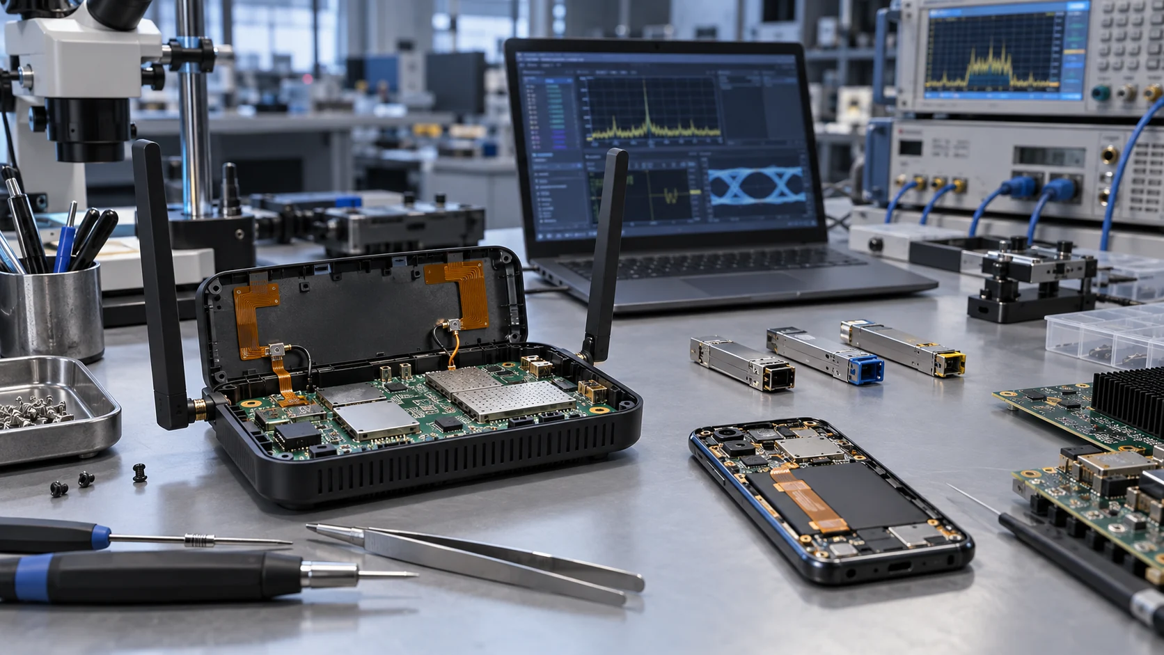
RF & Communication FPC Solutions
Custom RF flexible PCB and telecom interconnects for antenna modules, wireless terminals and high-speed communication assemblies. Coordinate materials, signal paths, shielding and connector support with Teleconix before prototype release.
Explore Solutions
Smart Automotive Electronics FPC
Teleconix delivers advanced flexible interconnects for ADAS, in-vehicle infotainment, powertrain control, and battery management systems — engineered for performance in intelligent automotive systems.
Explore Solutions AI & Robotics & Special Industrial FPC
Overcome severe mechanical stress and extreme spatial constraints in your automated hardware. We design and manufacture custom flexible circuits engineered to endure over 2 million continuous bending cycles in multi-axis robotic joints, bionic grippers, and autonomous AGV/AMR platforms.
Explore Solutions RF & Communication FPC Solutions
Custom RF flexible PCB and telecom interconnects for antenna modules, wireless terminals and high-speed communication assemblies. Coordinate materials, signal paths, shielding and connector support with Teleconix before prototype release.
Explore Solutions Smart Automotive Electronics FPC
Teleconix delivers advanced flexible interconnects for ADAS, in-vehicle infotainment, powertrain control, and battery management systems — engineered for performance in intelligent automotive systems.
Explore SolutionsFrequently Asked Questions
Conclusion: release a robotics interconnect with clear evidence
A robotics FPC project becomes easier to source when the team defines the interface, installed route and motion acceptance together. Distinguish stationary and moving regions, support the connector ends and preserve the evidence for the actual construction and revision. A general flexibility claim cannot replace those decisions.
To prepare an OEM review, discuss your robotics FPC requirements with Teleconix. Share the sensor and connector documents, mechanical route, available manufacturing files and the intended verification scope. Confirm the requested fabrication, assembly and testing services for your individual project before authorising the build.