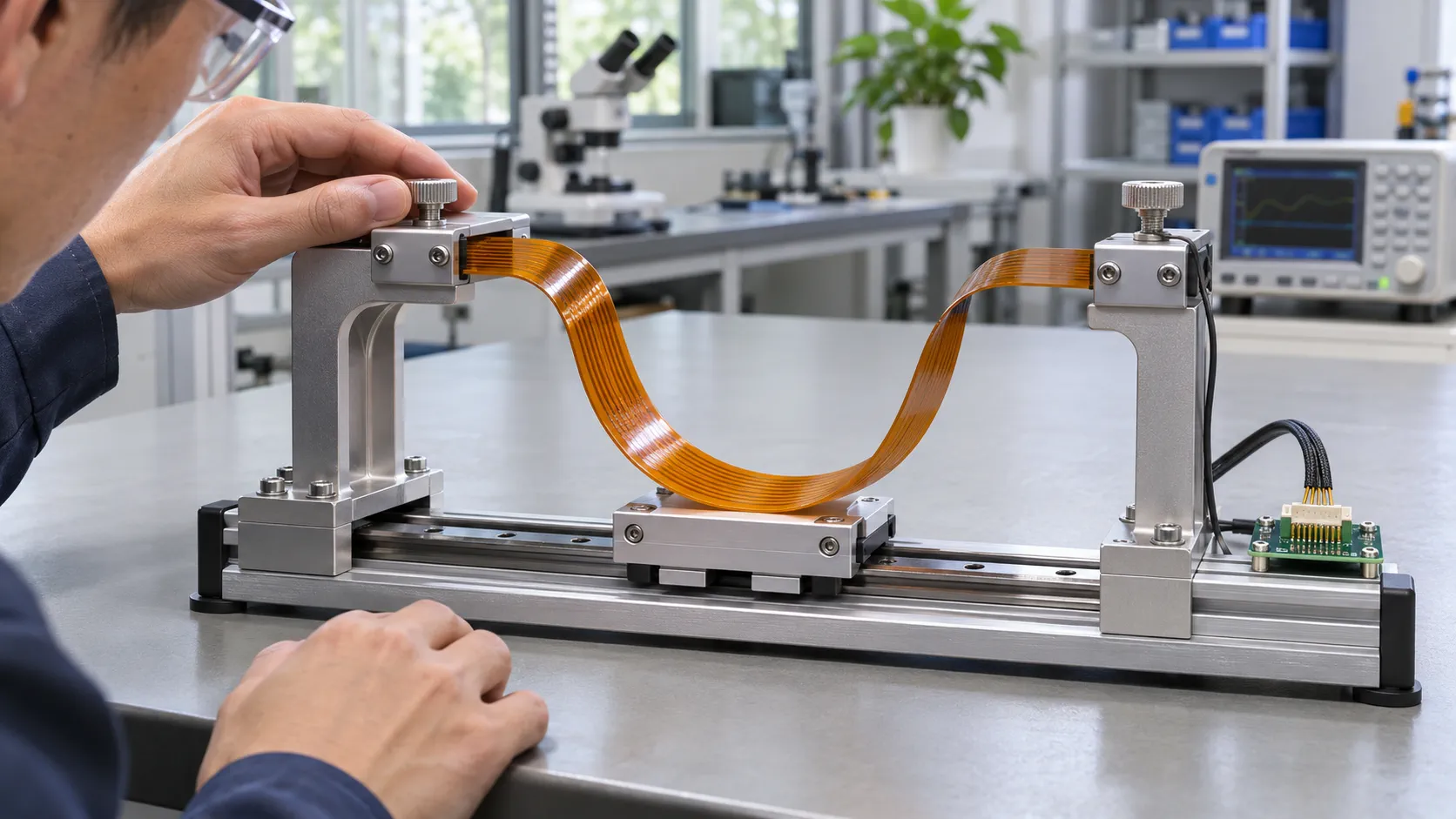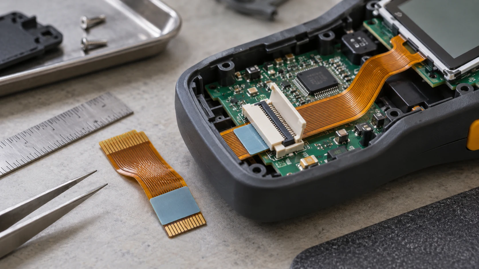

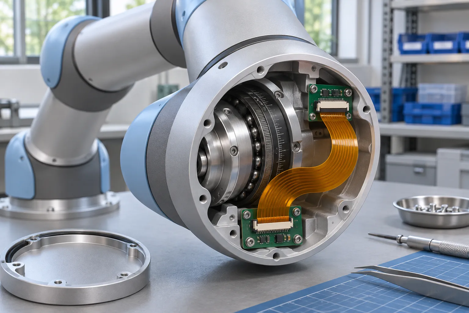
Robot joint FPC planning starts with the two interfaces
A robot joint FPC connects defined electrical interfaces while accommodating the space, support and movement inside the joint. Start with the two board interfaces and the installed route between them. The circuit outline comes from those requirements. A ribbon that fits an open housing can still become trapped when the cover is fitted or pull at a connector during motion.
This guide focuses on the handoff between mechanical design, electronics, assembly and purchasing. It helps an OEM team describe a robotic arm flexible PCB in a form that can be reviewed, quoted and checked on a representative build. For a broader overview of sensor functions and motion requirements, use the robotics FPC motion and sensor guide. Here, the release question is more specific: can this joint route be installed consistently and operate within its agreed boundaries?
Create an interface drawing before detailing the copper pattern. Label each end, show which board remains stationary, and identify the part that moves. Record the connector orientation, the assembly access and the reference coordinate system. Ask the mechanical and electronics owners to approve the same drawing. This prevents a mirrored tail or reversed mating face from reaching the prototype stage unnoticed.
Use three documents to start the review
- An interface map identifying every connector, board, signal group and responsible engineer.
- An installed route drawing showing supports, moving regions, travel limits and neighbouring hardware.
- An acceptance worksheet linking each requirement to an inspection or test and its reviewer.
Keep assumptions visible. If the connector, motion range or housing revision is provisional, mark that item and assign an owner. A supplier can then distinguish a confirmed manufacturing input from an open design decision. The approved circuit data should reference these documents so later changes remain traceable.
Separate limited joint travel from continuous rotation
Define the relative movement across the connection, not only the robot's advertised axis count. A flex mounted inside a moving arm may remain fixed relative to both of its endpoints. Another span may cross the rotating interface and change shape on every movement. Mark those regions separately, including movement introduced when a technician opens a cover.
For a limited-travel joint, provide the home position, both travel limits, intermediate positions and the sequence between them. State whether the moving span bends in one plane, experiences torsion, slides against a guide or combines these actions. A broad loop shown in a neutral pose does not establish what happens near the end stops. Have the responsible designer describe the actual motion before choosing a construction.
A finite flex loop should not be assumed to accommodate unlimited continuous turns. If continuous rotation is required, review the complete interconnect architecture with the system designer, including how electrical paths cross that interface. Keep the architecture decision separate from the fabrication quotation. It is more useful to resolve that boundary early than to ask a circuit manufacturer to infer it from an outline.
Write a movement record that another team can reproduce
Give each operating mode a name and attach the relevant mechanical views or controller sequence. Record the starting pose, ending pose, direction, dwell and any coupled axis movement that affects the connection. Include occasional service positions if they change the route. Identify who approves the normal-use envelope and who assesses abnormal loading.
Use the static and dynamic flex bend guide when describing bending conditions. Determine the working geometry from the complete construction and application review. Avoid applying a generic bend multiplier or lifetime number without checking its definition, specimen and conditions.
Review the swept route and its tolerance boundaries
Review the space occupied by the flex throughout travel, including the positions between the familiar assembly photographs. Check where the loop approaches a bearing shoulder, screw head, cover rib, moving bracket or adjacent cable. Note where a change in shape could produce a local fold, rub point or pinch. Record both the intended free route and any surfaces designed to guide it.
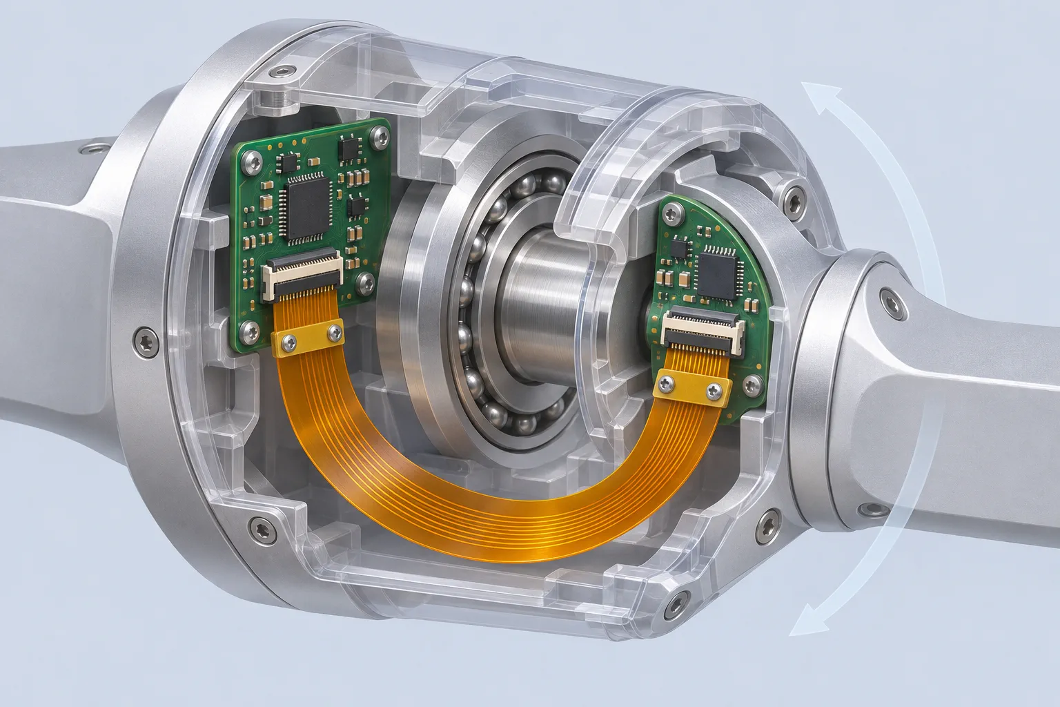
A useful review includes more than the nominal model. Consider the permitted board position, support position, circuit outline and assembly variation. Decide which combinations need a physical check. The team should agree the required clearance and how it will be assessed; the supplier should not choose a universal margin for every robot. Show the datum used to locate the tail so the measurement can be repeated.
Record the route at the decision points
| Joint condition | Check to document | Evidence to retain |
|---|---|---|
| Home and travel limits | Loop shape, contact and end loading | Identified views of both circuit faces where accessible |
| Intermediate movement | Local buckling, sliding and unexpected route changes | Observation linked to the motion sequence |
| Housing closure | Cover ribs, fasteners and trapped excess length | Assembly inspection and closed-build checks |
| Service position | Access, temporary support and permitted handling | Service instruction and relevant fit review |
Use a physical mockup to investigate how the circuit settles between supports. Treat it as a fit review with a named configuration, not as endurance evidence. If the mockup leads to a route change, revise the drawing and repeat the affected checks before ordering the next build.
Specify connector tails, supports and transition regions
Release the exact connector part number and its current mating drawing for each end. Check contact side, pin numbering, exposed contact length, finished tail thickness and insertion direction. Add the latch access needed during assembly and service. Matching pitch and conductor count alone does not confirm a usable interface.
The Hirose FH52 series information illustrates why the actual connector matters: it identifies a particular contact orientation and accepted FPC thickness. Its handling documentation also addresses insertion and tensile loading. Use the instructions for the selected part, rather than transferring those details to every ZIF connector. Component documentation is an input to the assembly review, not a qualification of the finished joint.
Identify where the tail is supported and where that support ends. The intended moving span should not obtain its movement by pulling the mating contacts or working a stiffener edge. Define reinforcement and adhesive as part of the local finished construction. Include the thickness measurement location and any areas where the support must not extend.
Make support placement a controlled assembly step
A drawing can show the clamp, locating feature or approved support method with a datum and inspection view. Record how the installer knows the tail is seated and whether the latch is closed. Avoid leaving clamp position, tape placement or excess-length storage to individual judgement. A repeatable method makes later samples easier to compare.
Use the flexible PCB stiffener checklist to review reinforcement thickness and transitions. Then try the finished tail in the actual connector with the surrounding hardware present. Record permitted mating and service operations. If a connector or reinforcement changes, return that local interface to the fit and handling review.
Map encoder, control and motor-related electrical paths
Identify the job of each conductor before combining paths into one robot joint FPC. Separate encoder communications, sensor supplies, control lines and any power path in the interface record. Record pin names, reference connections, connector contacts and the responsible electronics owner. Establish which paths actually belong on the flex and which use another connection in the joint.
Texas Instruments' TIDA-010979 robot joint reference design combines motor control, encoder interfaces and industrial communication in a compact platform. It is an example of several electrical functions sharing a joint, rather than evidence of any Teleconix current or power rating. Use the selected electronics documents to define the interconnect's actual requirements.
For encoder links, identify the protocol and physical interface. Analog Devices' AN-1397 motor encoder interface application note discusses different encoder interfaces, transceivers and timing considerations. This supports checking the complete interface, not copying a generic differential pair or encoder pinout. Ask the system designer to approve routing constraints, reference paths and any termination or shielding arrangement.
Review electrical changes with the installed route
Document the operating states relevant to the connection, including the motor and communication activity that the system team wants checked. Identify local heat sources and the circuit's proximity to them. If a power path is included, define load, voltage-drop, contact and thermal acceptance requirements from the actual design. Copper weight by itself does not establish a finished assembly rating.
Where controlled impedance is a specified requirement, use the controlled impedance planning guide to organise stack-up and verification inputs. Review the mechanical consequences of additional copper or shielding too. A change intended to help one electrical function may alter the moving construction, connector fit or available route.
Build a repeatable installation and diagnostic sequence
Write the assembly sequence while the mechanical design can still accommodate it. Identify the safe, unpowered assembly condition, board supports, connector access and order of cover installation. Show how to handle the circuit without using the moving span as a pull tab. Ask an assembly reviewer to try the instruction on a representative build and record unclear steps.
Check identity and fit before applying power. Confirm the circuit revision, correct endpoint, contact orientation, seating and support location. Move the mechanism through the approved inspection sequence under the project's safe procedure. Then inspect the route after closure, because a cover can change an otherwise acceptable loop. Retain photographs with the sample identifier and assembly revision.
Investigate symptoms with a condition record
If an encoder drops out, record the joint pose, direction of travel, operating state and observed fault before changing the assembly. Note whether the symptom is repeatable and which measurement captured it. Change one relevant condition at a time under a controlled investigation. Repeated reseating or uncontrolled bending can introduce another fault and obscure the original observation.
The flex PCB electrical testing guide explains the scope of bare-circuit connectivity checks. A passing netlist test is useful starting evidence, but it does not establish correct encoder timing, firmware behaviour or installed immunity. Keep the fabrication check, connector inspection and powered system check as identifiable steps with their own acceptance rules.
Preserve suspect samples with their history. Record whether a route, support or connector change affects the symptom, and identify which tests need repeating after the change. Feed the approved correction back into the assembly drawing so production receives an instruction rather than an informal workshop workaround.
Agree prototype acceptance for the actual joint configuration
Define what the prototype decision will release. A first fit build may approve connector access and a proposed route. A later configuration may support motion or system-level verification. State which questions each build must answer and which remain open. This prevents a useful mechanical demonstration from being presented as complete qualification of the robot.
Identify the specimen construction, circuit and enclosure revisions, support hardware, motion program and environment. Choose the sample plan and acceptance limits with the responsible engineering and quality reviewers. Include records that distinguish a circuit issue from a fixture, connector or measurement issue. Keep the result linked to the exact configuration tested.
Separate the acceptance checks
- Identity and construction: drawing revision, material proposal, reinforcement and approved substitutions.
- Installed fit: seating, support position, route through travel and enclosure closure.
- Electrical function: agreed checks before motion, during relevant operating states and after testing.
- Motion evidence: a defined sequence, monitoring arrangement, endpoint and response to an interruption or failed sample.
For repeated movement, use the flex PCB fatigue testing checklist to develop the detailed endurance plan. A cycle count becomes meaningful when the specimen, geometry, movement and failure rule are known. Keep results from different configurations separate unless the responsible reviewer establishes a defensible comparison.
Set a review gate before release. Record the decision, outstanding limitations and conditions that require another check. A housing adjustment, support relocation or material substitution may affect previously accepted observations. Assess that change explicitly and preserve the earlier evidence rather than silently treating it as approval of the new build.
Package a robot joint FPC RFQ with clear review ownership
Send a quotation package that links fabrication data to the installed joint. Include the outline, layer information, proposed construction, connector drawings and local support details. Add the interface map, mechanical views and acceptance worksheet developed above. If populated delivery is requested, include the BOM, placement data, assembly drawing and ownership of customer-supplied components.
Use a release manifest to identify file names and revisions. State quantities for prototype and later production separately, together with the requested inspection and reporting scope. Ask the quotation to list assumptions, alternatives and exclusions. Review fabrication, assembly tooling, components and testing as named items so proposals can be compared on the same basis.
Example: close a wrist routing decision before purchase
Consider an illustrative OEM wrist with a fixed controller board and a moving sensor board. The initial drawing shows a flex between them but leaves the support position undecided. The team first agrees the limited travel and both connector interfaces. It then checks the loop with the cover and fasteners installed, records the approved supports and updates the route drawing.
The supplier quotes against that revision and states any remaining construction assumptions. The prototype order identifies the fit and electrical checks to complete before the motion programme. Purchasing holds the next build until the named reviewers accept the evidence or release a documented revision. This is a planning example, not a Teleconix customer case or a measured performance result.
Before authorising production, close open decisions or record their permitted limits. Confirm which organisation owns circuit design, installed routing, test execution and final product approval. Keep approved changes with the order so a later reorder uses the intended configuration. A clear responsibility record is particularly useful when a robot joint FPC is sourced alongside motors, sensors and mechanical parts from different suppliers.
Related Robotics and Industrial FPC Products
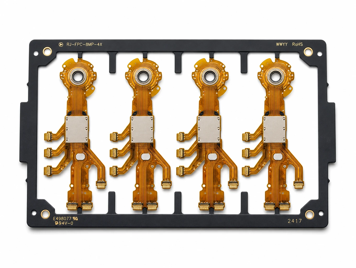
Multi-Branch Humanoid Robotic Joint FPC
Model: TLX-ROB-JNT01
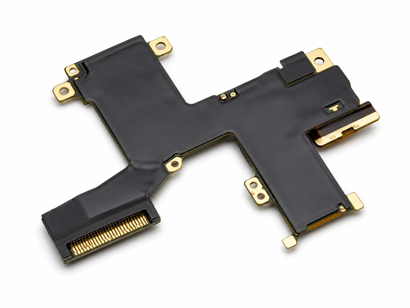
Micro-Form Factor Haptic Surgical Robotics Flex Circuit
Model: TLX-ROB-MED05
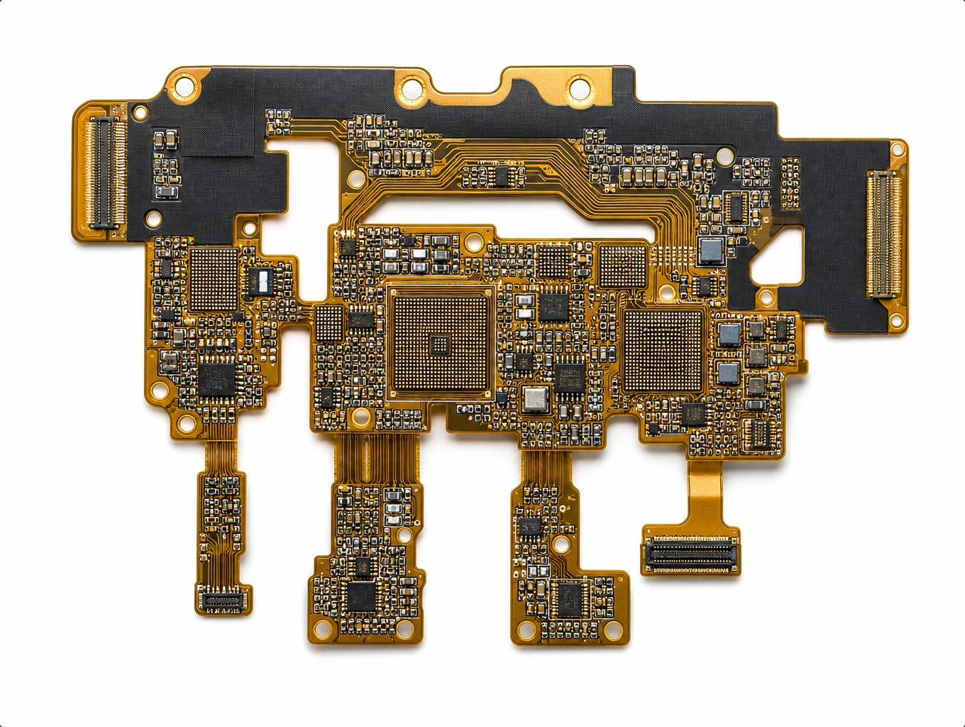
High-Speed AI Vision & LiDAR Sensor Matrix FPC
Model: TLX-AI-VIS02
Related FPC Application Solutions

AI & Robotics & Special Industrial FPC
Flexible circuits for robotic joints, vision sensors, actuators and industrial interfaces. Match the circuit route to the motion, electrical connections and enclosure of your machine.
Explore Solutions
RF & Communication FPC Solutions
Custom RF flexible PCB and telecom interconnects for antenna modules, wireless terminals and high-speed communication assemblies. Coordinate materials, signal paths, shielding and connector support with Teleconix before prototype release.
Explore Solutions
Medical Device FPC Solutions
Custom flexible circuits for diagnostic equipment, patient monitoring and compact medical electronics. Discuss routing, signal paths, materials and prototype acceptance with Teleconix before releasing your OEM design.
Explore Solutions AI & Robotics & Special Industrial FPC
Flexible circuits for robotic joints, vision sensors, actuators and industrial interfaces. Match the circuit route to the motion, electrical connections and enclosure of your machine.
Explore Solutions RF & Communication FPC Solutions
Custom RF flexible PCB and telecom interconnects for antenna modules, wireless terminals and high-speed communication assemblies. Coordinate materials, signal paths, shielding and connector support with Teleconix before prototype release.
Explore Solutions Medical Device FPC Solutions
Custom flexible circuits for diagnostic equipment, patient monitoring and compact medical electronics. Discuss routing, signal paths, materials and prototype acceptance with Teleconix before releasing your OEM design.
Explore SolutionsFrequently Asked Questions
Conclusion: release the joint route and its evidence together
A robot joint FPC project becomes easier to review when its electrical interfaces, limited motion, supported ends and installed route share one controlled revision. Use the prototype to answer defined fit and operating questions, then preserve the observations behind the release decision. Confirm the construction and verification scope for the actual joint rather than relying on a general flexibility claim.
To prepare a project review, discuss your robot joint FPC requirements with Teleconix. Share the connector documents, installed mechanical views, circuit data, expected motion and acceptance requirements. Confirm fabrication, assembly and testing responsibilities for your individual project before placing the build order.