
Flexible PCB stiffener selection starts with its purpose
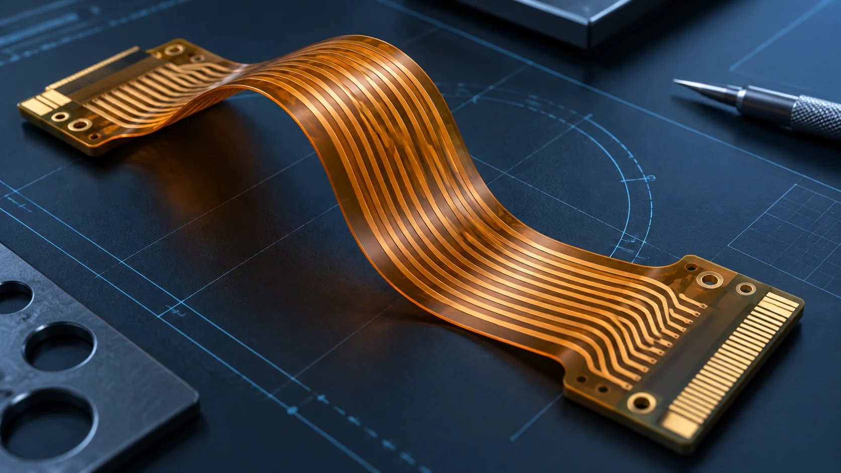
A flexible PCB stiffener adds local mechanical support to a flexible circuit. It may help a connector tail reach the required mating thickness, keep an assembled area stable, or provide a defined surface for handling and mounting. The flexible portion still needs room to follow its intended route without being forced against a sharp support edge.
For OEM teams, the useful starting question is what the supported region must do. A tail inserted into a socket, a soldered connector island and a mounting location have different loads and dimensional requirements. Record the function before selecting a material or copying a thickness from a previous design.
This guide focuses on reinforcement decisions, drawings and acceptance checks. Use the flexible PCB materials guide for the wider copper, dielectric and coverlay discussion. The construction examples are design concepts; confirm the actual material system and available manufacturing scope for your project.
Separate permanent reinforcement from temporary assembly tooling
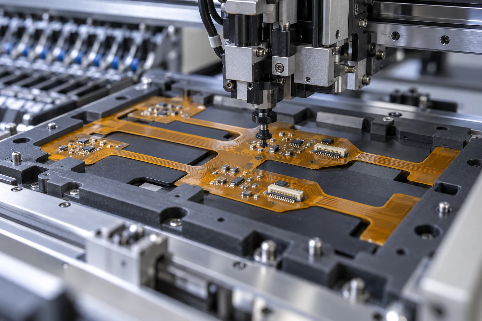
A permanent stiffener remains attached to the delivered circuit. A temporary carrier or fixture supports the flex during printing, placement, soldering or inspection and is removed according to the assembly process. Both can stabilize an assembly, but they belong to different specifications, purchasing responsibilities and inspection steps.
Identify each support explicitly on the drawing. State whether it is part of the shipped product, part of the delivery panel or an assembly tool. A supplier should not need to infer this from a shaded shape in the Gerber data. For tooling, identify who designs it, who owns it and what information the assembler needs.
A circuit with an attached support is not automatically an integrated rigid-flex PCB. Electrical layer continuity and the regional construction define that architecture. See the rigid flex PCB design and sourcing checklist when the project requires populated rigid regions connected within one circuit construction. Keep those requirements separate from a simple reinforcement note.
Compare polyimide, FR4 and metal support by function
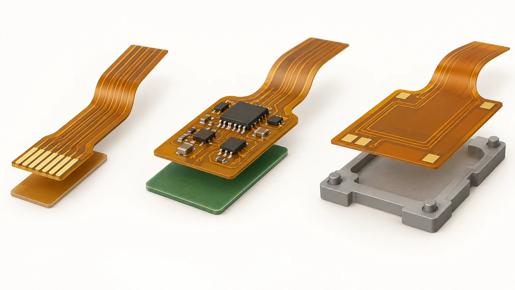
Material selection should reflect the mechanical job, available space, attachment method and assembly environment. Polyimide reinforcement can be considered for a connector tail where thickness adjustment and a thin profile matter. FR4 can provide a more rigid supporting area. A metal support introduces additional considerations for insulation, edges, mass and any intentional electrical connection.
Avoid purchasing by material name alone. Specify the grade or an agreed material specification, nominal thickness, tolerance and bonding system. Ask the supplier to identify a proposed substitute before approval. A change from one adhesive system to another can affect the complete finished thickness even if the support material stays the same.
Würth Elektronik describes glued FR4 mechanical stiffeners in its PURE.flex rules. That example demonstrates a defined construction, not a universal material or process requirement for every FPC. Compare candidates against your connector and enclosure drawings, then confirm the accepted construction with the responsible fabricator and assembler.
| Candidate | Typical design question | What to confirm |
|---|---|---|
| Polyimide reinforcement | Can the tail reach its mating thickness? | Complete tail stack and connector requirements |
| FR4 support | Does the local region need greater rigidity? | Outline, attachment, mounting and assembly access |
| Metal support | Is a special mechanical function justified? | Insulation, clearance, edges and electrical intent |
| Temporary carrier | How will the flex remain stable during assembly? | Tooling ownership, process and removal method |
Calculate connector thickness from the complete tail stack
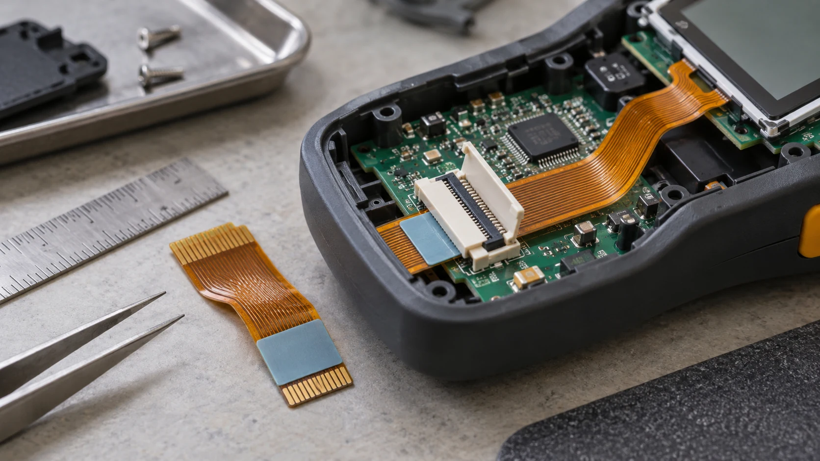
Connector fit depends on the thickness of the finished tail at the mating region. The support thickness by itself does not describe that measurement. Account for the circuit substrate, copper and finish, protective layers where present, reinforcement and its adhesive. Document which layers are present at the exact measurement location.
For a simple planning exercise, list the nominal contributions in a worksheet and compare their sum with the connector drawing. Then ask the supplier to confirm the final construction and tolerance. Do not assume every film has its catalogue thickness after bonding, or that independently specified layer tolerances can be ignored in the finished part.
The Hirose FH40 catalogue, for example, defines an applicable FPC thickness and illustrates the reinforcement construction. Its requirement belongs to that connector series. Obtain the drawing for the actual part number, including contact side, insertion depth and permitted variation, rather than applying an illustrative number to a different socket.
Define the measurement point, method and acceptance window on the released inspection plan. A nominally correct tail that varies outside the approved window can still create an assembly problem.
Confirm contact side, insertion direction and latch access
A reinforced tail can have the correct thickness and still be assembled incorrectly. Show the exposed contact side, the side receiving the stiffener and the insertion direction. Check those features against the selected connector orientation on the main board. A top-contact and bottom-contact interface may require different layouts and installation handling.
Review how an operator will hold the tail, insert it squarely and close the actuator. The available space changes after the enclosure and neighbouring components are installed. Identify the intended gripping area so that an operator does not pull a thin unsupported section or press a tool against the contact fingers.
Include practical installation views in the drawing package. A side view should show the tail entering the socket without a forced crease. An enclosure view should show access to the latch. Verify these details with the actual connector and representative parts; a rendered model helps communication but does not demonstrate successful mating.
Keep service removal in the same review when the device is intended to be repaired.
Place stiffener edges outside the intended bending zone
A support creates a boundary between a more rigid region and an unsupported flexible region. The enclosure route should give the flex room to bend in its intended location. Show the stiffener edge and the bend envelope together so reviewers can see whether the assembly forces a sharp change immediately at that boundary.
Do not select an overlap, setback or minimum bend radius from a generic illustration. Ask the fabricator for construction-specific guidance and explain whether the circuit bends only during installation or moves repeatedly in service. Provide the installed clearance, nearby supports and any expected handling during maintenance.
The flex PCB bend radius guide organizes those inputs. Here, the additional task is to make the reinforcement boundary visible in both the circuit drawing and the mechanical installation drawing. Check the real route after latching the connector and closing the housing, not just while the assembly is open on a bench.
Support component islands without creating enclosure loads
A flexible PCB with stiffener may support a connector, component group or local mounting area. The support should suit the loads created during assembly and use. Identify where insertion, screw tightening, pressing or handling forces enter the region, and what structure is intended to carry them.
Review the proposed support outline with component placement and soldering access. An underside reinforcement can affect fixture contact and clearance even when it is invisible in a top-view layout. Include any openings required by the assembly process, while confirming that the remaining material still performs its mechanical function.
Use the FPC assembly and quality control guide to coordinate the circuit with the assembler. Permanent support and temporary tooling may both be needed. Agree who verifies flatness, component seating and access before the process is released. A stiffener should not be treated as a substitute for an intentional mounting and load path in the finished device.
Specify the adhesive and attachment process as part of the design
The bonding layer is part of the reinforced construction. Record an approved adhesive specification or ask the supplier to propose one with the quotation. Clarify the assembly sequence and any temperature or environmental exposure relevant to the bond. An unspecified attachment method makes thickness, inspection and substitution harder to control.
Discuss the support side, bonding area, cutouts and features that must remain free of adhesive. Exposed contacts, connector alignment features and installation surfaces should be identifiable in the drawing. Specify observable acceptance conditions at accessible edges, together with any destructive or sample testing the project actually requires.
Avoid inventing a universal peel-strength limit or bonding temperature. Such limits need an agreed material, preparation method and test procedure. Ask for the proposed process and evidence appropriate to your application, then document the approved requirements in the order package.
If the adhesive changes later, review both bond performance and dimensional consequences before accepting the substitution.
Control the outline, registration and thickness datums
Release a separate reinforcement outline or clearly identified fabrication layer. Dimension its location from stable circuit reference features, identify the attachment side, and define relevant registration tolerances. A rectangle labelled stiffener without datums can be interpreted differently by the designer, fabricator and incoming inspector.
Distinguish support thickness from total finished thickness. Mark the measurement locations for each requirement, especially where a connector tail, component island and free flex have different constructions. Specify whether a dimension applies before assembly or to the complete delivered circuit.
Check the outline against coverlay openings, contacts, holes and the final enclosure. A small location change can move a support edge into the bend route or obstruct connector insertion. Include these relationships in the review instead of approving the stiffener drawing separately from the circuit.
Keep all drawings, fabrication outputs and mechanical models on one revision. An outline changed in CAD but not in the reinforcement file is a preventable source of inconsistent prototypes.
Check electrical consequences of an added support
Mechanical support can also affect the physical surroundings of an electrical path. Identify sensitive signal routing near the reinforced area and any conductive support or enclosure surface. A metal support needs a clear statement of whether it is isolated, connected intentionally or simply a mechanical part with controlled clearance.
For a controlled-impedance path, provide the actual regional construction to the person responsible for modelling. Do not assume that a reinforced section and an unsupported section share identical surroundings. Review the signal path through the connector and any transition as a complete interface.
The controlled impedance flex PCB planning guide explains the model, return-path and verification questions. Reinforcement selection should feed that review when the support changes the relevant geometry or materials. Electrical requirements and their acceptance methods belong in the released specification, rather than being inferred from a material name or a statement that the circuit passed continuity testing.
Use prototypes to verify fit, handling and supported regions
Build the first verification around the intended assembly sequence. Check the tail with the actual connector, inspect seating and latch access, and confirm the installed route. For a component island, check handling, fixture support and relevant enclosure contact. Record the part revision and the configuration used for each observation.
A useful prototype log separates dimensional checks from functional checks. Capture finished thickness at agreed locations, reinforcement position, outline fit and visible bond condition. Then record connector operation, assembly handling and whatever functional checks the product design requires. A photograph of a closed latch is useful evidence, but it is not a complete electrical or reliability result.
Plan this work with the flexible PCB prototype and validation guide. If the product moves, experiences vibration or undergoes environmental exposure, define representative conditions and acceptance criteria. Do not use one successful manual fold as evidence of repeated-motion life.
Write an RFQ that makes reinforcement quotations comparable
The RFQ should identify the circuit revision, support locations, proposed material and thickness, bonding requirements and acceptance scope. Include the connector part number and relevant mechanical drawing. If the construction is still open, ask suppliers to price a clearly described proposed solution and list assumptions rather than silently choosing different builds.
- Controlled circuit outline and reinforcement outline with attachment side.
- Proposed stack-up and finished thickness requirements at named locations.
- Connector drawing, contact orientation and assembly access.
- Material and adhesive specification or a documented proposal request.
- Inspection, prototype acceptance, packaging and order quantities.
- Separate pricing for tooling, samples, production and technical alternatives.
Review exceptions before comparing totals. One quotation may include a permanent support while another assumes temporary assembly tooling. The flexible PCB cost guide helps structure the wider comparison. Ask each supplier to state its actual manufacturing and testing scope; an application illustration does not confirm a particular process or qualification.
Link incoming inspection to the released reinforcement requirements
Incoming inspection should use the same datums, measurement locations and acceptance criteria agreed during design review. Check identification and revision first, then the reinforced features relevant to installation. Define sampling and records according to the project requirement, without assuming every dimension must receive the same inspection frequency.
When a part does not mate correctly, preserve the observation before changing the assembly. Check thickness, orientation, support location, insertion depth and the connector condition systematically. For a lifted support edge, record the location and visible condition, then compare it with the agreed bond acceptance criteria. Use the released specification to distinguish a manufacturing discrepancy from an incomplete design requirement.
Coordinate records with the FPC manufacturing quality guide. Continuity testing does not replace mechanical fit checks. A useful report connects the affected feature, sample identification, measurement method and disposition so the next build can be evaluated against a clear correction.
Review reinforcement changes before production release
Treat changes to the support material, thickness, adhesive, outline or attachment sequence as controlled design changes. Identify which connector, enclosure, assembly or electrical checks could be affected. A change that looks cosmetic in a flat drawing may alter the installed bend route or the completed mating thickness.
Require the supplier to document a proposed substitution before manufacture. Engineering should compare it with the approved package, record the decision and define any repeated checks. Purchasing should update the order references so the next lot is not built from an earlier assumption. Keep prototype findings with the released revision.
Technical references
For construction examples, consult Würth Elektronik PURE.flex design rules and its flex solutions design guide. For a connector-specific reinforcement and thickness example, see Hirose FH40 documentation. Use the documentation for your actual materials and connector; these references are not evidence of Teleconix certification or project approval.
Related Products
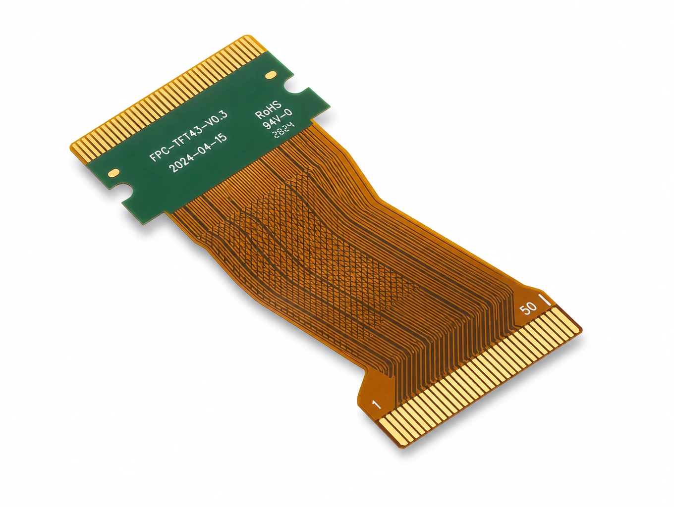
Industrial HMI & TFT-LCD Module FPC
Model: TLX-DFPC-IND05
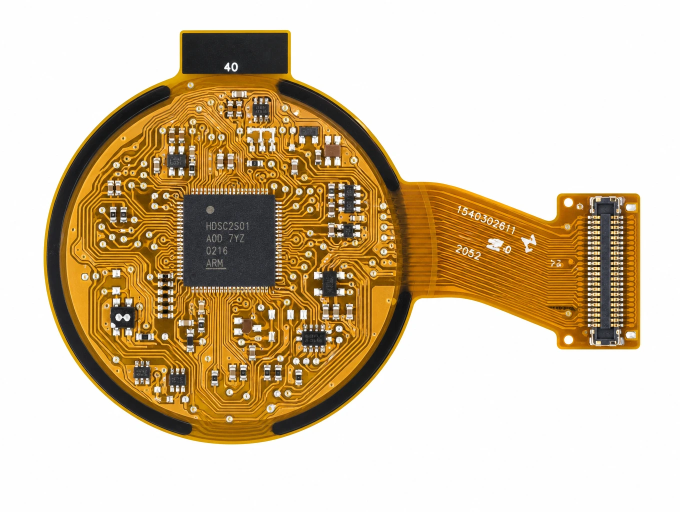
Wearable Smartwatch & Round AMOLED FPC
Model: TLX-DFPC-WEAR04
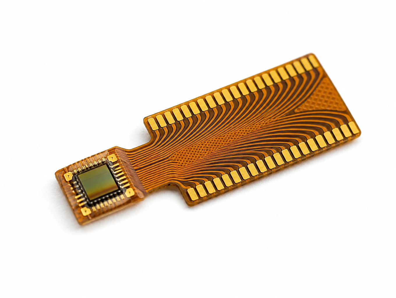
Medical Endoscope Micro-Display FPC
Model: TLX-DFPC-MED06
Related Solutions

Display FPC
Teleconix manufactures fine-pitch, high-density FPCs for LCD, OLED, mini-LED displays, camera modules, and optical sensors — delivering stable signal transmission and exceptional brightness control.
Explore Solutions
Medical Device FPC Solutions
Custom flexible circuits for diagnostic equipment, patient monitoring and compact medical electronics. Discuss routing, signal paths, materials and prototype acceptance with Teleconix before releasing your OEM design.
Explore Solutions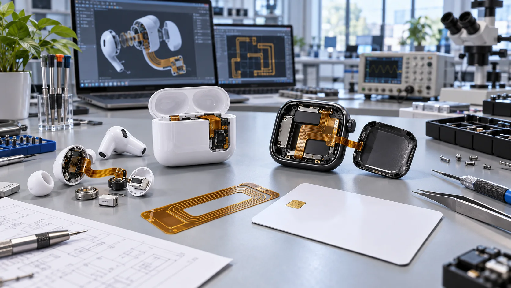
Consumer Electronics & Smart Card FPC Solutions
Custom flexible circuits for smart cards, TWS earbuds and compact wearables. Align routing, stack-up, component interfaces and prototype acceptance with Teleconix before releasing your OEM design.
Explore Solutions Display FPC
Teleconix manufactures fine-pitch, high-density FPCs for LCD, OLED, mini-LED displays, camera modules, and optical sensors — delivering stable signal transmission and exceptional brightness control.
Explore Solutions Medical Device FPC Solutions
Custom flexible circuits for diagnostic equipment, patient monitoring and compact medical electronics. Discuss routing, signal paths, materials and prototype acceptance with Teleconix before releasing your OEM design.
Explore Solutions Consumer Electronics & Smart Card FPC Solutions
Custom flexible circuits for smart cards, TWS earbuds and compact wearables. Align routing, stack-up, component interfaces and prototype acceptance with Teleconix before releasing your OEM design.
Explore SolutionsFrequently Asked Questions
Conclusion: release a controlled stiffener specification
A flexible PCB stiffener works best when its purpose, complete thickness, boundaries and verification requirements are defined together. Coordinate the connector, circuit, enclosure and assembly process before choosing a support by material name. Keep the approved construction and acceptance record under revision control.
Prepare the reinforcement drawing, connector information and installation requirements, then discuss your flexible PCB project with Teleconix. Use the OEM and ODM project page to organize the wider sourcing package. Confirm the proposed manufacturing scope and project-specific evidence before releasing production.