


Introduction
The FPC manufacturing process converts a controlled design package into a thin circuit that must still meet electrical, dimensional and mechanical requirements. For an OEM buyer, a list of factory steps is only the beginning. The useful question is how the supplier controls the inputs, records decisions and verifies the finished circuit against the released revision.
Flexible circuits can differ in layer count, copper type, coverlay, stiffeners, plated holes, surface finish and installed bend duty. Those choices change the process route and the evidence needed for approval. A single-layer static tail and a multilayer dynamic flex should not share an identical inspection plan.
This guide follows a practical flexible PCB fabrication sequence while showing what engineering, quality and purchasing teams should review at each stage. Use it together with the flexible PCB design guidelines, the flexible PCB materials guide and the approved project drawing. The actual route and inspection plan must always be confirmed with the selected supplier.
For the shared circuit definition that precedes manufacturing review, see what is a flexible PCB, including FPC, FFC and rigid-flex distinctions for OEM teams.
Release controlled data before manufacturing begins
Manufacturing should begin from one released package rather than a collection of email attachments. The package normally includes fabrication data, a dimensioned drawing, stack-up, materials, copper requirements, coverlay openings, stiffener details, surface finish, critical tolerances and the electrical test basis. Add the BOM and assembly files when the scope includes components.
Give every file the same revision identifier. The supplier should acknowledge the received revision and return any assumptions or exceptions before tooling starts. If a drawing conflicts with the fabrication data, the conflict needs a documented answer instead of an operator choosing one source informally.
A useful release review separates mandatory requirements from preferences. The bend zone, connector interface, finished thickness and critical outline dimensions may be essential, while a general note copied from an older program may not apply. Removing ambiguous or obsolete notes reduces the chance that two suppliers manufacture different products from the same RFQ.
Prepare and verify flexible circuit materials
The process route starts with the approved material system. Copper-clad dielectric, bondply or adhesive, coverlay, stiffener material, shielding film and protective layers should match the released stack-up or an approved equivalent. Incoming verification can include identity, thickness, lot information, condition and storage status according to the supplier's control plan.
Material handling matters because thin films can collect damage, contamination or dimensional change before imaging. The exact cleaning, conditioning and storage method depends on the selected material and facility. An OEM does not need to prescribe every internal work instruction, but it should require the supplier to preserve material identity and notify controlled substitutions.
When an alternative is proposed, compare more than the material name. Review dielectric thickness, copper type and weight, adhesive system, coverlay construction, availability and the effect on bend or assembly conditions. The flex PCB stack-up selection guide provides a structured way to document that decision.
Image and etch the copper pattern
Imaging transfers the released conductor pattern to the copper surface. Etching then removes unwanted copper and leaves the required traces, pads and features. The supplier's process must control conductor geometry, registration and surface condition within the drawing requirements.
Fine traces and spaces reduce process margin when combined with thin copper, dense routing or tight tolerances. Buyers should identify the smallest recurring geometry and the truly critical features instead of quoting only one minimum value from the design. This helps the supplier evaluate the entire pattern rather than a single isolated dimension.
Inspection at this stage may use optical methods and process coupons, depending on the construction and control plan. The objective is not merely to find a visibly broken trace. It is to confirm that the imaged pattern can proceed to later lamination, plating and finishing steps without carrying an avoidable defect forward.
Control registration, drilling and plated features
Double-sided, multilayer and rigid-flex constructions may require drilled holes, laser-drilled features, plated-through connections or other interlayer structures. The specific sequence depends on the stack-up. Registration between copper layers, holes and external features becomes part of the manufacturing control plan.
The drawing should distinguish plated and non-plated holes, finished sizes, tolerances and any blind, buried or microvia structures. Critical annular rings and connector features need a clear acceptance basis. A generic note such as “standard vias” does not define the finished requirement.
For an OEM review, ask how the supplier verifies the plated connection and which evidence is delivered for the project. Electrical testing confirms the network, while physical inspection or representative microsection evidence may be required for characteristics that electrical test cannot reveal. The buyer and supplier should agree the sample plan and record format before production.
Laminate the stack-up and apply coverlay
Lamination joins the controlled dielectric, copper and bonding layers into the required construction. Coverlay protects conductors while leaving designed openings for pads, contacts and other exposed features. Pressure, temperature, alignment and material behavior are managed through the supplier's qualified process for the selected stack-up.
Coverlay openings should align with pads and keep sufficient support around bend transitions and interfaces. Adhesive flow, trapped contamination, wrinkles and misregistration are examples of conditions that a supplier may evaluate during process and final inspection. The acceptance decision still follows the drawing and agreed specification, not a general photograph on a website.
Active bend areas deserve particular attention. Layer transitions, coverlay edges, copper direction and local thickness changes should match the released design. Use the flex PCB bend radius and support guide to connect the manufacturing review with the installed static or dynamic bend condition.
Add surface finish, stiffeners and local features
Surface finish protects exposed copper and supports the intended connector, soldering or bonding interface. The released drawing should state the required finish and identify selective contact or plating zones. Connector fingers, solder pads and wire-bond areas may have different functional requirements.
Stiffeners create controlled local thickness and mechanical support. Their material, thickness, outline, bonding method and alignment affect connector engagement, component support and assembly handling. A stiffener should therefore be treated as part of the finished stack-up rather than an accessory added without dimensional control.
Shielding films, pressure-sensitive adhesive, reinforcement, protective tape and formed features can add separate operations. The supplier should confirm which features are included in the quotation and which require customer-supplied tooling or a later assembly step. This avoids discovering at first article inspection that the quoted part stops before the required finished configuration.
Profile the outline and separate finished circuits
The final outline may be formed by routing, punching, laser cutting or another controlled method suitable for the design and production volume. The chosen method affects tooling, edge condition, dimensional control and the way circuits are held in a manufacturing array.
Array rails, breakaway features, tooling holes and coupons support processing but do not belong to the installed part unless the drawing says otherwise. The supplier should return the proposed panel or array when it affects assembly handling, traceability or cost. Purchasing can then compare quotations against the same delivered format.
Thin circuits need support during separation and handling. Excessive bending, sharp tools, debris or poorly controlled tabs can damage conductors or coverlay near the edge. Define critical outline features and bend-adjacent keep-outs clearly, then use dimensional and visual inspection to verify the finished result.
Use electrical testing to verify the released network
Electrical testing checks whether conductive networks are connected according to the released design and whether unintended connections are present. The test data, fixture strategy and limits depend on the circuit, quantity and procurement requirements. A flying-probe method and a dedicated fixture can serve different production conditions.
Continuity and isolation results do not prove every physical characteristic. They cannot by themselves confirm finished outline, coverlay alignment, plating condition, conductor geometry or bend reliability. Electrical test should therefore sit inside a broader acceptance plan rather than act as the only quality gate.
The RFQ should state whether every finished circuit requires test, how failures are controlled, and what record or certificate is delivered. When functional testing is also required, separate it from the bare-board electrical test and define the needed connectors, fixtures, power limits and pass criteria.
For the test input and acceptance records, use our flex PCB electrical testing guide to align netlist revisions, continuity and isolation coverage, retest rules, and lot release evidence.
Inspect visual, dimensional and internal characteristics
Visual inspection reviews observable conditions such as conductor and pad appearance, coverlay registration, surface finish, contamination, marking and edge quality. Dimensional inspection verifies the characteristics that control fit, connector engagement and assembly. Internal characteristics may require representative samples or other agreed evidence.
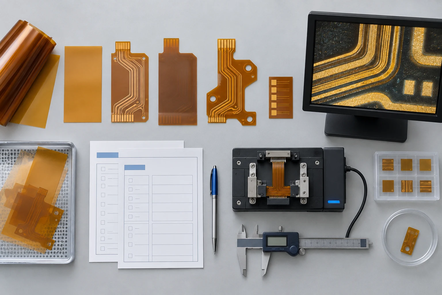
IPC describes IPC-A-600 as a visual interpretation of minimum printed-board requirements and notes that the applicable design and performance specifications still govern the product. Buyers can review the current IPC-A-600 acceptability overview and the IPC document revision table when defining their procurement baseline.
The purchase documentation should identify the applicable revision, product class or project-specific acceptance agreement. Do not assume a supplier certificate, website claim or generic inspection report automatically covers the construction being ordered.
Require traceable quality records instead of generic claims
Quality control becomes useful when the record connects to the delivered lot and revision. A practical package may include material identity, traveler or routing information, inspection results, electrical test status, nonconformance disposition and shipment traceability. The exact set should match the project's risk and purchasing requirements.
| Review point | Evidence to define | Buyer question |
|---|---|---|
| Released data | Revision acknowledgement and exceptions | Which file set controlled production? |
| Materials | Specified material or approved equivalent and lot identity | Were substitutions approved before use? |
| Process | Traveler, in-process checks or controlled routing | Which route applied to this construction? |
| Inspection | Critical dimensions and visual acceptance results | Which characteristics were actually measured? |
| Electrical test | Test basis, status and failure control | Was every required finished circuit tested? |
| Change control | Deviation, concession and revision history | What changed from the approved baseline? |
A certificate should not replace the underlying definition. If the OEM needs numerical reports, sample retention or lot-specific data, state that requirement before quotation. This allows the supplier to price and plan the real documentation scope.
Approve prototypes and first articles against one baseline
A prototype proves more than whether the circuit powers on. It should confirm the released construction, fit, connector interface, assembly behavior, installed bend condition and inspection plan. The buyer should record which deviations are acceptable for prototype learning and which must be corrected before production.
First article review should compare the sample with the same drawing, stack-up and quality requirements used for the quotation. If the supplier proposes a material, panel or tooling change after the prototype, the change needs a new technical decision. Otherwise, a production lot may differ from the sample that engineering approved.
Close open questions with controlled records. Approvals hidden in meeting notes or personal email are difficult to trace during a later failure review. Link the accepted sample, revision and any concessions to the production baseline.
Use the flexible PCB prototype validation guide to define sample objectives, installed fit checks and the evidence needed before production transfer.
Scale from prototype to production with controlled changes
Production scale can change panel quantities, tooling, material purchasing and inspection frequency. The product requirements should remain stable unless engineering approves a revision. Ask the supplier to identify which prototype controls will carry forward and which production controls will replace them.
Use a defined notification route for changes to material source, stack-up, tooling, process location, test method or subcontracted operation when those items matter to the approved product. The objective is not to freeze every internal improvement. It is to prevent a material change from reaching production without the review required by the project.
Commercial effects should be linked to the same change record. The flexible PCB cost and quotation guide explains how to separate recurring price, tooling, testing and revision-related charges when moving from prototype to regular releases.
Protect thin circuits during packaging and delivery
Inspection is not the final risk point. Flexible circuits can be damaged by uncontrolled bending, stacking, abrasion, contamination or packaging that forces the part into an unintended shape. The packaging method should support the finished outline and exposed contact areas through transport and incoming inspection.
Define the delivered format: individual circuits, arrays, trays, bags or another agreed configuration. State labeling, lot separation and any handling or cleanliness requirements that the next operation needs. For assembled circuits, include protection for components and connectors as well as the flexible tail.
Incoming inspection should confirm identity, quantity, packaging condition, revision and the project-specific evidence package before the lot enters assembly. A clear receiving check helps detect documentation or handling issues before value is added to the circuit.
Avoid common RFQ gaps and audit the complete route
Common gaps include sending Gerber data without a stack-up, leaving the bend duty undefined, mixing drawing revisions, omitting stiffener tolerances, and asking for “full testing” without naming the test. Another gap is assuming that a generic factory capability list applies to every material, geometry and volume.
Build the supplier review around the actual route. Ask who controls each manufacturing and inspection stage, which operations are subcontracted, how released data reaches production, and how deviations are approved. Request project evidence rather than unsupported best-quality or zero-defect claims.
Use open questions as part of the audit trail. Give each question an owner, due date and effect on quotation or release. When the supplier answers, update the controlled package or record the approved exception instead of leaving the decision in an isolated message. This is especially useful when engineering, purchasing and quality teams review the same project at different times. A closed question should point to the drawing note, material approval, sample result or commercial assumption that resolved it.
Before quotation, use the Teleconix OEM and ODM project handoff to organize fabrication data, stack-up, quantities, assembly scope and quality expectations. During review, connect each requirement to a drawing note, specification, report or approval owner. This makes the final manufacturing baseline clear to engineering, purchasing and quality.
For a populated build, use the FPC assembly RFQ and quality control guide to define component sourcing, support fixtures and assembly-level acceptance alongside the fabrication requirements.
Related Products
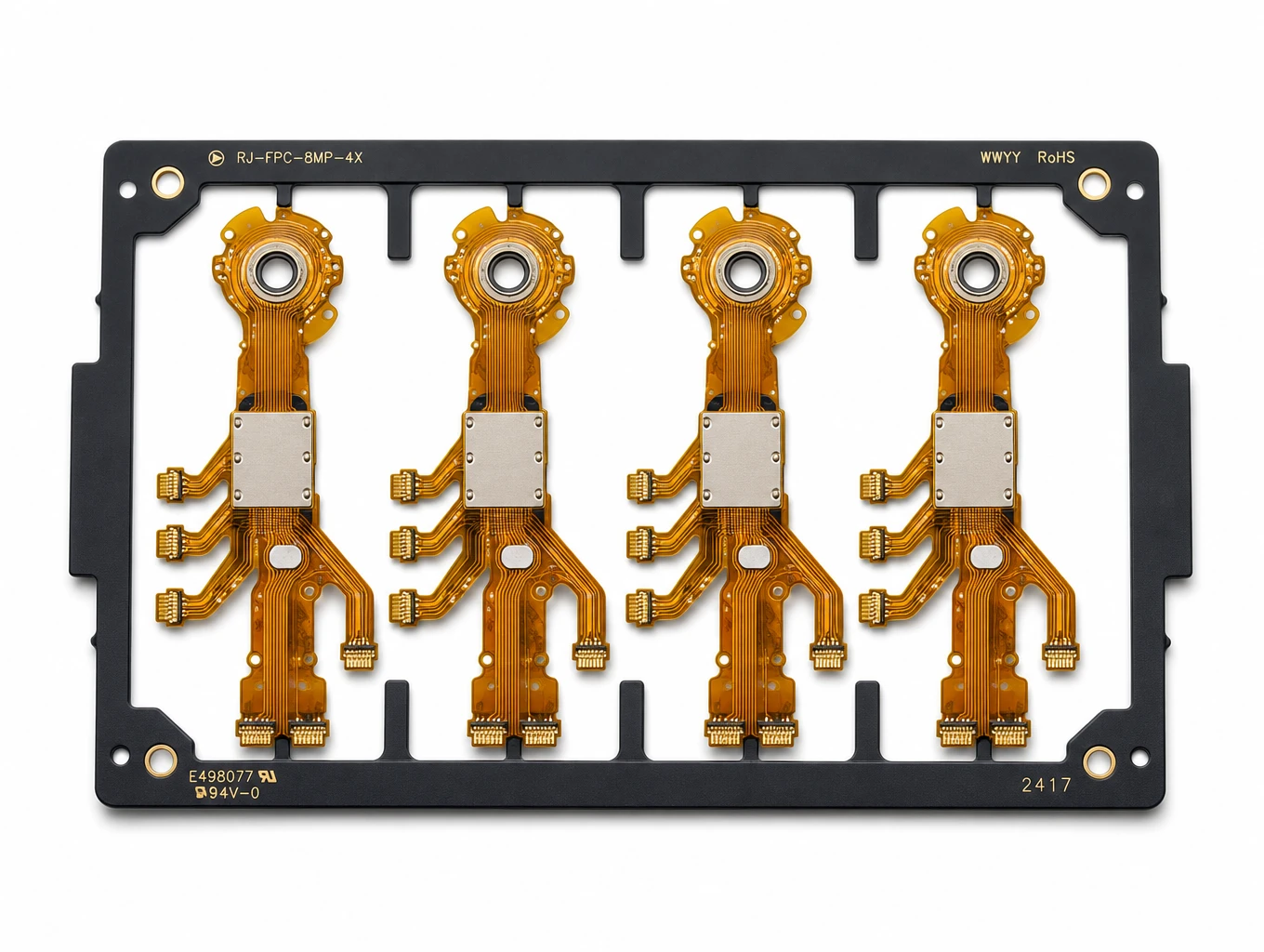
Multi-Branch Humanoid Robotic Joint FPC
Model: TLX-ROB-JNT01
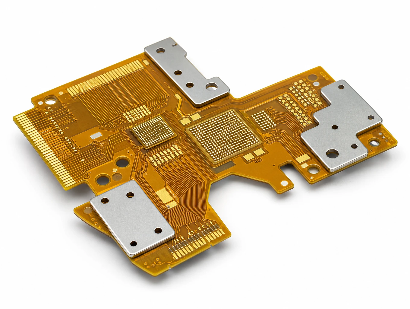
400G/800G High-Speed Optical Transceiver Multi-Layer Flex PCB
Model: TLX-COMM-OPT03
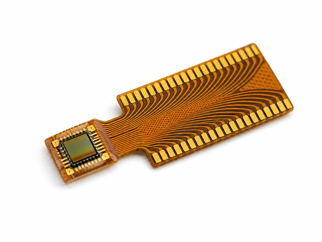
Medical Endoscope Micro-Display FPC
Model: TLX-DFPC-MED06
Related Solutions

AI & Robotics & Special Industrial FPC
Flexible circuits for robotic joints, vision sensors, actuators and industrial interfaces. Match the circuit route to the motion, electrical connections and enclosure of your machine.
Explore Solutions
Smart Automotive Electronics FPC
Automotive FPC products for battery monitoring, ADAS cameras, radar, cockpit displays, steering controls and LED lighting. Select a starting configuration by module function and installation needs.
Explore Solutions
Display FPC
Display FPC products for OLED, AMOLED, micro-LED and TFT-LCD modules in handheld, wearable, automotive and industrial devices. Review the display interface, connector and installed flex shape together.
Explore Solutions AI & Robotics & Special Industrial FPC
Flexible circuits for robotic joints, vision sensors, actuators and industrial interfaces. Match the circuit route to the motion, electrical connections and enclosure of your machine.
Explore Solutions Smart Automotive Electronics FPC
Automotive FPC products for battery monitoring, ADAS cameras, radar, cockpit displays, steering controls and LED lighting. Select a starting configuration by module function and installation needs.
Explore Solutions Display FPC
Display FPC products for OLED, AMOLED, micro-LED and TFT-LCD modules in handheld, wearable, automotive and industrial devices. Review the display interface, connector and installed flex shape together.
Explore SolutionsFrequently Asked Questions
Conclusion: connect every manufacturing step to evidence
The FPC manufacturing process should be reviewed as a controlled chain from released data and materials through imaging, lamination, finishing, profiling, testing, inspection and delivery. Each step needs a clear input, an acceptance basis and a record appropriate to the project.
For an OEM, the goal is not to copy a supplier's internal procedure into the drawing. It is to define the product, critical characteristics, evidence and change-control boundaries well enough that the supplier can build and verify the same approved revision repeatedly.
To discuss a project-specific route, send the current fabrication package, stack-up, quantities, bend condition, assembly scope and test expectations through the Teleconix project inquiry form. The team can return the technical questions that should be resolved before quotation and prototype release.