

Define which connection the foldable phone FPC must carry
A foldable phone FPC is a flexible printed circuit connecting specified electronics inside a folding handset. It may serve a display module, a connection between rigid assemblies or another compact interface. Its requirements come from the endpoints and the installed route. The folding display itself, its mechanical support and the FPC interconnect are different parts of the design.
For an OEM team, the useful starting point is an interface map showing the host, display, touch controller and any other connected assemblies. Name the exact connection being quoted. A stationary display tail folded during installation is different from an interconnect that crosses a moving hinge on every opening cycle. Both may be called a phone flex cable, but that description is not a specification.
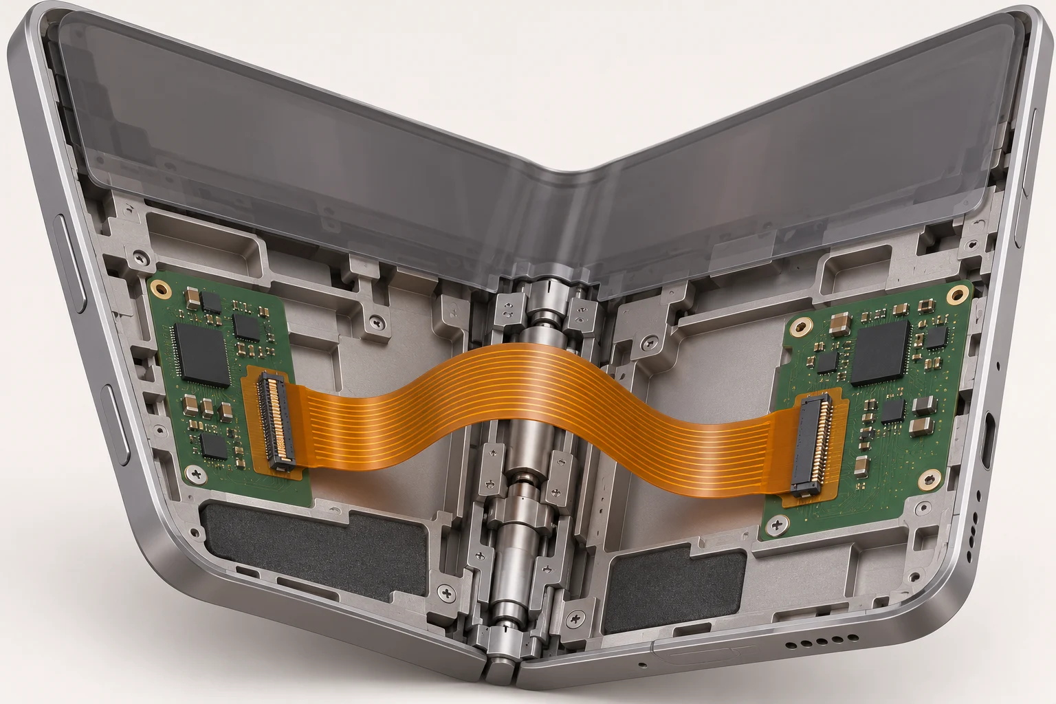
Samsung's July 2024 view inside the Galaxy Z Fold6 shows the display, supporting wing plate, hinge and board assemblies as separate elements. It is a useful example of system packaging, not a construction drawing for another handset or evidence that one generic FPC fits all foldables.
Choose a clear delivery boundary
State whether the requirement covers a bare circuit, a populated interconnect or a larger module. A circuit supplier cannot infer which display electronics, shielding, connectors or assembly operations are included from a photograph of an opened phone. Record the proposed scope and the information that still needs approval.
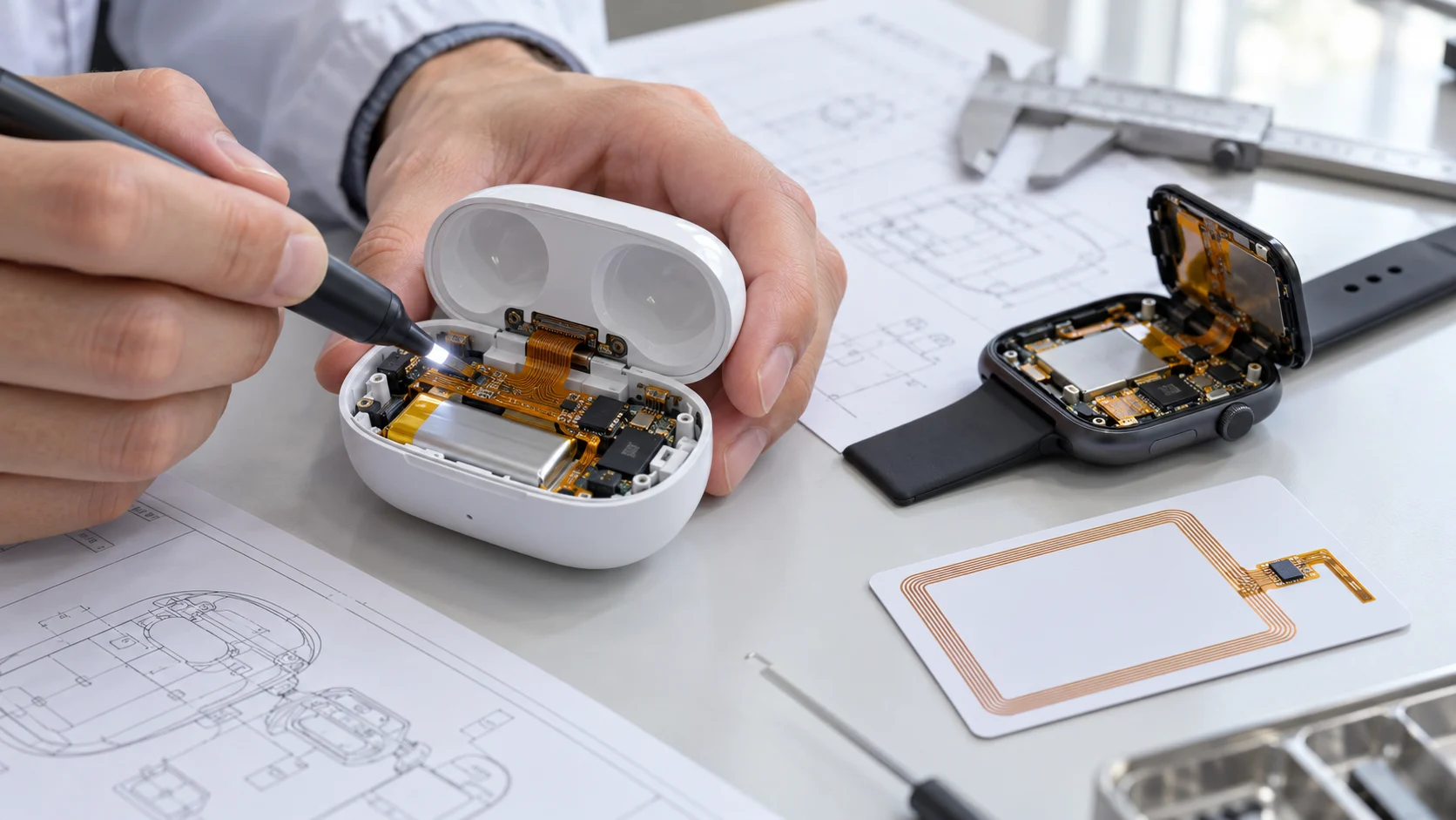
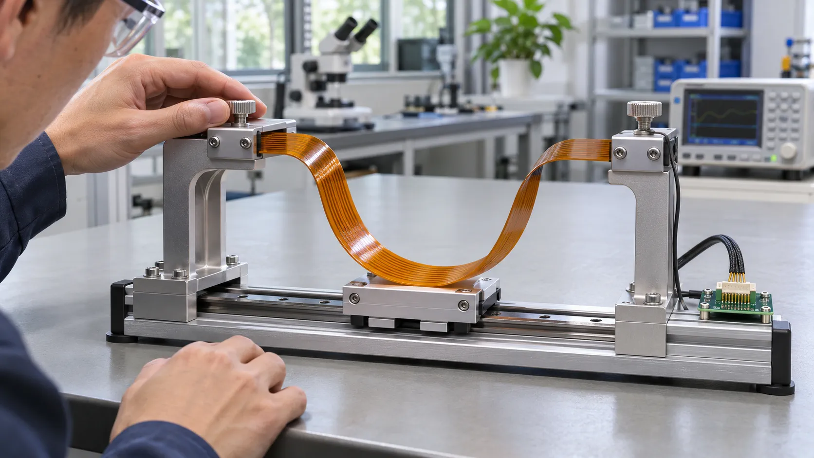
Our consumer electronics FPC integration guide covers the broader device review. This article narrows that review to foldable handset interfaces, hinge packaging and staged validation. The photographs and cutaway here are generated concepts for explanation; they do not represent a verified Teleconix customer device or released manufacturing geometry.
Map the hinge route throughout the complete folding sequence
Review the entire route through movement, rather than approving an attractive open-phone pose. The available space changes as the two rigid halves rotate and the hinge mechanism moves. The circuit must retain its intended path without being trapped, pulled tight or pushed into a nearby component.
| Design state | Mechanical questions | Record to retain |
|---|---|---|
| Expanded handset | Is the free span supported as intended, with clearance from hardware? | Installed view, restraint positions and circuit revision |
| Intermediate angles | Does the loop sweep into a hinge part, screw boss or another cable? | Agreed motion sequence and interference observations |
| Closed handset | Is any region pinched, sharply folded or pressed against the housing? | Closed geometry and relevant tolerance assumptions |
| Assembly and service | Can the connector be reached without bending an unsupported tail? | Assembly order, permitted handling and replacement boundary |
Use the approved hinge and enclosure revision for the review. A changed cover, adhesive pad or restraint position can alter the route even when the circuit artwork stays the same. Include the parts that occupy the clearance envelope, rather than checking a bare hinge on its own.
Describe the deformation that actually occurs
Separate recurring bending from installation folds, sliding contact and any unintended twist. If several branches share a limited passage, check how they move together. Do not assume that an unused gap in one pose remains available throughout the sequence. Ask the mechanical owner to identify the route and support surfaces before the circuit outline is released.
The flex PCB bend radius guide explains why movement classification matters. Select the geometry with the proposed construction and supplier review; a minimum-radius number copied from a different stack-up does not establish suitability for this hinge.
Choose the stack-up for the moving span and the fixed regions
Review the complete construction in each mechanical region. Base film, copper, adhesives, coverlay and any shielding contribute to the finished circuit. A material family name or total nominal thickness alone does not describe how the installed interconnect will behave.
Identify the moving span, connector lands, component areas and transitions on the same drawing. Agree where construction changes are permitted and how they are controlled. If the electrical design needs additional conductors, discuss whether the architecture or region construction can address that requirement without assuming that the entire hinge span must use one unchanged multilayer stack.
Keep material evidence tied to its conditions
Sumitomo Electric's 2008 technical review of FPC development discusses how materials and local construction affected repeated-bending applications. Its historical folding-phone examples concern earlier handset architectures. They support reviewing construction carefully, not transferring an old specimen result to a modern folding-screen phone.
Ask the supplier to identify the proposed copper, dielectric, adhesive and protective layers, including any alternates. Rolled annealed copper may be considered for a dynamic application, but the foil designation is not a finished-assembly life guarantee. Compare the documented proposal and relevant evidence, rather than treating all rolled copper as interchangeable or all electrodeposited copper as unsuitable.
Use the adhesiveless flex PCB selection guide when comparing base-laminate options. Removing a base-laminate adhesive does not mean the complete assembly has no adhesive; coverlay, support and attachment features still need review.
Define the transition from a stiffened or attached area to the free moving span. A support that improves connector handling may shift deformation to its boundary. Inspect that boundary as part of the route, together with coverlay openings, exposed features and other local changes. Approve the actual construction and installed arrangement before requesting a meaningful validation result.
Specify display and host interfaces before setting routing constraints
Define the electrical connection from the selected display module and host documents. Screen technology, pixel count and a familiar-looking connector do not establish the interface, pin assignment, supply requirements or approved lane configuration. Keep the display tail and a separate board-to-board hinge interconnect distinct in the interface map.
Our display FPC integration guide covers the host, display and connector information needed for this step. Capture the module part number, revision, contact orientation and relevant electrical instructions. Where touch and display signals share an assembly, document both functions instead of assuming that a working image verifies the complete interface.
Agree which measurements belong to the circuit and which to the system
If controlled impedance is required, specify the actual nets, construction assumptions and acceptance method. Agree who assesses the complete channel, including connector and board transitions. A circuit coupon measures its specified structure; it does not by itself verify the installed display channel or prove operation in every folding position.
Define supply and return paths using the actual loads. Narrowing a branch to fit a hinge does not establish that it can carry the required current without a thermal or voltage-drop review. Conversely, adding shielding or return conductors may affect construction and packaging. Resolve those trade-offs with the electrical and mechanical owners together.
Identify the relevant operating conditions for checking signal behaviour. These may include the selected display mode, touch operation and other system activity defined by the OEM. A failure at an intermediate hinge position should be recorded with its mechanical state and electrical configuration, so that the investigation can separate routing, mating, circuit and system causes.
Do not add high-speed labels or precision tolerances merely to make the quotation look more complete. Every special requirement should have an owner, a reason and an agreed verification method. Unspecified system assumptions should remain open decisions rather than becoming implied supplier guarantees.
Control connector mating, support and access inside the handset
The connector region needs its own review, outside the moving-span discussion. Identify both mating components and confirm the required contact side, insertion direction, exposed contact geometry and finished mating thickness from their drawings. Pitch and conductor count alone do not prove interchangeability.
Hirose's FH52 series documentation is one example of a connector family that specifies mating thickness and contact orientation. It is cited to illustrate the need for part-specific documents, not as a recommendation to use that connector in a foldable phone. The selected handset connector must meet its own packaging and electrical requirements.
Distinguish mating thickness from moving-circuit thickness
A supported flex tail can have a different finished construction from the free span. Include the stiffener and its adhesive in the mating review when applicable. Show where support ends and ensure that routine connector insertion does not put an uncontrolled crease into the adjacent circuit. Use the flexible PCB stiffener guide to structure that support definition.
Check access with the actual housing and nearby parts in place. A connector that mates easily on a bench may be difficult to inspect behind a hinge cover or shield. Define the assembly order, permitted tools and seating or latch inspection method. Do not assume a connector is fully engaged because the handset powers on once.
Show the intended cable restraint and any attachment area. A restraint should control the route without pressing a critical region against an edge or forcing the free span to absorb assembly variation. The relevant tolerances belong in the review, particularly where several parts combine to determine the available gap.
Agree how the interconnect is disconnected for rework or service. If replacement requires disturbing a bonded display or another sensitive assembly, record that dependency with the module owner. The circuit supplier should not promise a simple field replacement procedure without approval of the complete device assembly process.
Make installation and handling part of the controlled design
Write the installation sequence before treating the outline as final. Show which half receives each end first, when restraints are applied and which parts must remain accessible. Include any temporary support needed to prevent a free branch from being folded or pulled while other components are fitted.
Review the circuit in the state delivered to the assembler. Bare circuits, connector-populated assemblies and preformed subassemblies may require different handling instructions. Agree whether any shape is formed during supply or only during installation, and who verifies that operation. A photograph of a formed sample is not sufficient process control.
Remove ambiguous assembly choices
Identify branch orientation and circuit revision clearly. Where two similar tails connect nearby, the drawings should prevent an incorrect mating or reversed route. Use suitable marking or other agreed controls where the construction allows them. Do not rely on a technician recognizing the intended route from a generic concept image.
Define inspection points before the route becomes hidden. Check connector engagement, support placement, visible damage and the free span at the stage when each can still be inspected. Record any rework and the acceptance check needed afterward. Repeatedly opening a housing for troubleshooting should not become an unrecorded extra handling condition.
When populated supply is requested, prepare a BOM, placement data and assembly drawings consistent with the circuit revision. Our FPC assembly guide outlines the additional assembly inputs. Specify which fixtures, inspection records and component alternatives require OEM approval, rather than adding them as assumptions after a quotation is accepted.
Keep cleanliness, adhesive placement and environmental exposure in the agreed assembly plan. Their relevance depends on the actual route and module design. A bare-circuit material rating does not establish compatibility with every joining process, cleaning agent or finished handset environment.
Validate bare circuits, installed interconnects and the folding device separately
Define staged acceptance with a clear meaning for each pass. Circuit inspection and electrical testing establish the agreed circuit condition. An installed interconnect assessment adds mating, support and the route. The handset validation then evaluates the approved system configuration under its relevant operating and environmental conditions.
| Acceptance level | Review scope | Evidence boundary |
|---|---|---|
| Bare circuit or supplied assembly | Released construction, inspected features and specified electrical checks | Does not establish finished phone folding life |
| Installed hinge interconnect | Clearance, connector loading, defined motion and relevant signal checks | Applies to the recorded route, fixture and revision |
| Integrated handset | Display and touch behaviour, folding sequence and approved system conditions | Owned by the OEM's complete device validation plan |
Samsung's 2019 account of Galaxy Fold testing describes repeated folding as part of a particular device assessment. Such a device result cannot be reused as a rating for a separately quoted FPC. Record the actual sample, fixture, motion, environment and failure criteria for the assembly being approved.
Capture a baseline and investigate changes
Record the circuit and module revisions, connector condition and relevant electrical baseline before the defined motion sequence. Repeat the agreed observations during or after movement, as appropriate to the plan. Inspect the route and support areas as well as checking whether the display still operates. Note intermittent behaviour with the corresponding folding state.
The flex PCB fatigue testing guide explains why a cycle count needs its test conditions. The OEM should define the required sample plan, acceptance limits and approval stages. A material designation, a successful bench demonstration or a general supplier statement does not replace that plan.
When an issue appears, retain the assembly state and configuration information before replacing parts. An image fault may involve the display, connector, host, software or interconnect. Investigate the evidence rather than immediately identifying every fold-related symptom as a copper fatigue failure.
Release a foldable phone FPC RFQ with explicit decisions and evidence
An effective request for quotation links the foldable phone FPC to an identified handset connection and a controlled revision. It gives suppliers enough information to explain their construction proposal, exclusions and verification scope without guessing the display or hinge architecture.
- Interface map: exact endpoints, display and connector references, pin assignments, signal and supply requirements and approval owners.
- Circuit package: artwork or agreed CAD data, outline, holes, proposed regional stack-up, finish and critical fabrication requirements.
- Installed mechanics: hinge and enclosure revision, complete motion sequence, support and restraint positions, clearances and assembly access.
- Supply scope: bare or populated delivery, BOM and assembly information where relevant, identification and handling instructions.
- Acceptance plan: separate circuit, installed-interconnect and device checks, fixtures, reports, sample requirements and release gates.
- Commercial basis: prototype and production-stage quantities, requested documentation and how changes or open engineering decisions will be addressed.
The flexible PCB RFQ manufacturing-file guide covers the common fabrication documents. Add the handset interface map and motion evidence, rather than replacing those documents with a product rendering.
Compare like-for-like quotations
Check whether proposals cover the same construction, connector scope, assembly operations and tests. Ask suppliers to identify tooling, fixture development, alternate materials and exclusions. A bare-circuit price and a populated, fixture-tested module price answer different purchasing questions.
Before the order is released, close open requirements or assign them to an approval gate. Keep the agreed stack-up, mechanical route, assembly instructions and acceptance plan linked to the ordered revision. When the display, hinge or housing changes, review the affected documents together and repeat the relevant checks. That controlled handoff is more useful than a generic promise that the circuit is thin, flexible and suitable for every folding phone.
Related Products
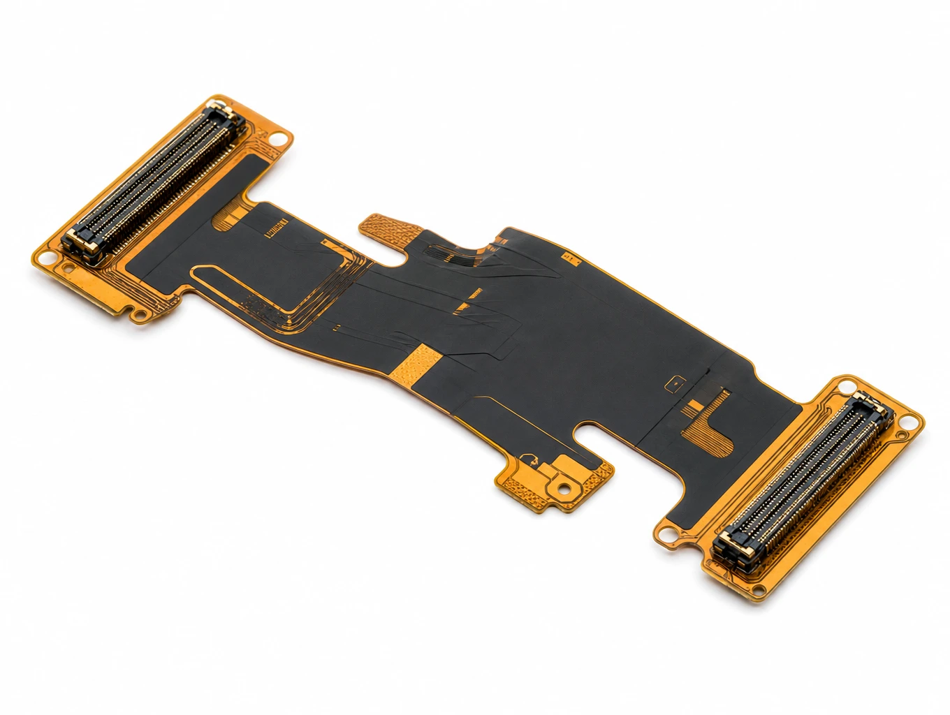
Foldable Smartphone Dynamic Hinge Multi-Layer Interconnect FPC
Model: TLX-COMM-FOLD02
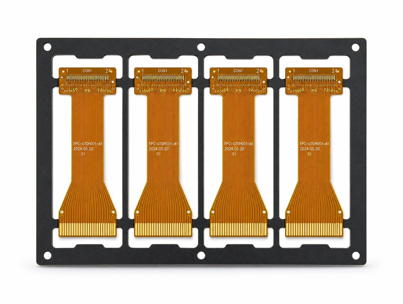
Ultra-Thin AMOLED & OLED Driver FPC
Model: TLX-DFPC-OLED01
Related Solutions

Consumer Electronics & Smart Card FPC Solutions
Custom flexible circuits for smart cards, TWS earbuds and compact wearables. Align routing, stack-up, component interfaces and prototype acceptance with Teleconix before releasing your OEM design.
Explore Solutions
Display FPC
Display FPC products for OLED, AMOLED, micro-LED and TFT-LCD modules in handheld, wearable, automotive and industrial devices. Review the display interface, connector and installed flex shape together.
Explore Solutions Consumer Electronics & Smart Card FPC Solutions
Custom flexible circuits for smart cards, TWS earbuds and compact wearables. Align routing, stack-up, component interfaces and prototype acceptance with Teleconix before releasing your OEM design.
Explore Solutions Display FPC
Display FPC products for OLED, AMOLED, micro-LED and TFT-LCD modules in handheld, wearable, automotive and industrial devices. Review the display interface, connector and installed flex shape together.
Explore SolutionsFrequently Asked Questions
Conclusion: agree the installed foldable phone interconnect
A foldable phone FPC should be designed around a specified interface and the complete installed folding route. Separate display-module requirements from hinge-interconnect requirements, control mating and support details, and agree what each validation stage establishes.
Share your display and connector references, circuit data, installed hinge views and prototype acceptance requirements with Teleconix. Discuss your foldable phone FPC project to review construction assumptions, delivery scope and open OEM decisions before ordering.