

Introduction
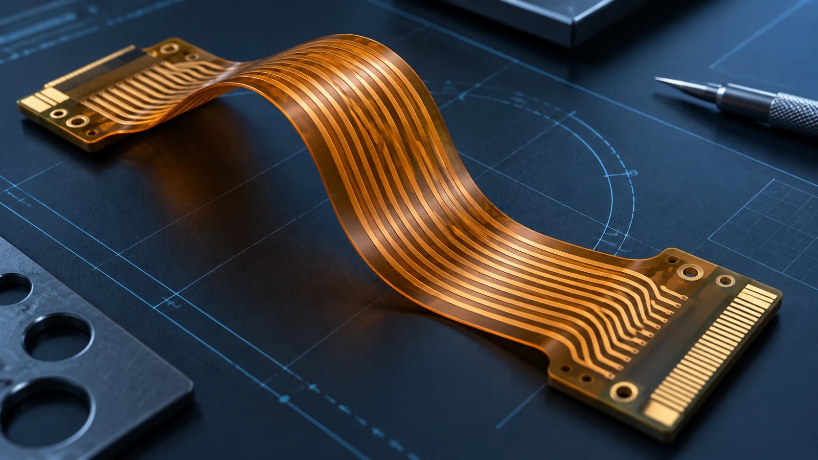
FPC assembly turns a bare flexible circuit into an interconnect or electronic assembly with attached components. For an OEM, the key purchasing question is whether the proposed build includes the right materials, controlled placement, mechanical support and tests for the installed application. A populated circuit that looks acceptable on the bench can still be difficult to insert, route or inspect in the product.
This guide helps engineering, quality and procurement teams prepare an assembly RFQ, review supplier assumptions and approve a first article. It focuses on decisions that should be recorded before an order: what is supplied, how fragile areas are supported, which inspections are required and what evidence authorizes production transfer.
If your team is still defining the construction, start with the flexible PCB basics guide. The assembly review below complements that foundation rather than replacing the circuit design review.
Define FPC assembly, FPCA and the delivery boundary
The abbreviation FPCA commonly refers to a flexible printed circuit assembly. The term alone does not specify whether the supplier provides a populated circuit, adds a connector, sources every component or delivers a tested module. Write the delivery boundary in the quotation and purchase order instead of expecting both parties to interpret the abbreviation identically.
Bare circuit fabrication and assembly require related but different information. Fabrication defines the copper pattern, dielectric construction, coverlay, finishes and reinforcement. Assembly adds component identification, placement, soldering or attachment requirements and inspection. Final enclosure installation introduces further routing, retention and functional requirements that may belong to the OEM.
Name the organization responsible for each step, including subcontracted work. Ask which records travel with the lot and who approves a change. A circuit fabricator and a separate assembler can work successfully together when their handoff is clear; an unclear boundary can leave an important requirement unowned.
Release one consistent assembly file package
Supply fabrication data and a dimensioned drawing together with the bill of materials, placement data and assembly drawing. Identify the revision of each file. Specify the agreed data format and coordinate origin so the assembler can reconcile component positions with the copper and outline. Resolve conflicting revisions before tooling or procurement starts.
The assembly drawing should identify the component side, polarity, reference designators, connector orientation and areas where parts or tooling must not intrude. Include views that explain folded routing and local reinforcement. Mark important dimensions and acceptance criteria directly rather than relying on a photograph that lacks a scale or controlled revision.
Request a written list of questions and assumptions from the supplier. Close each question through the same release process used for design changes. Email can document the discussion, but the manufacturing package should capture the accepted result so a later operator does not have to reconstruct decisions from an incomplete conversation.
- Controlled fabrication files, drawing and stack-up.
- BOM with manufacturer part numbers and approved alternatives.
- Placement coordinates, orientation conventions and assembly notes.
- Inspection, test, packaging and required lot records.
Clarify component sourcing and substitution authority
Decide whether the assembly is turnkey, consigned or a mixed arrangement. A turnkey quotation may include component procurement, while a consigned build depends on material provided by the customer. For a mixed build, mark responsibility for each BOM line. State how shortages, damaged parts and unused customer stock will be handled.
Approved alternatives need engineering criteria, not just similar descriptions. A connector with the same pitch can have different mating thickness, latch geometry or contact orientation. A substitute package can change pad compatibility, assembly access or thermal behavior. Require approval before a substitution enters the build and update the controlled BOM accordingly.
Confirm sourcing channels and traceability requirements for components whose provenance matters to the application. Record the evidence requested with the shipment. The RFQ should also distinguish production parts from optional development substitutions, since a prototype assembled with an alternative component may require additional validation before repeat orders.
Keep component islands outside the intended bend zone
A flexible tail can route between supported areas while a populated island carries components. Review the installed geometry so bending does not load component bodies, solder joints or a connector attachment unintentionally. Mark the intended flexible region and the supported region on the drawing, including the transition between them.
Evaluate the complete installation sequence. An operator may temporarily fold a tail while reaching a connector even when the final routing is gentle. Nearby enclosure ribs, clamps and fasteners can change where strain develops. Use a representative mechanical assembly to check these conditions instead of evaluating only the flat circuit.
Use the flex PCB bend radius guide to define static or repeated-motion conditions. Do not specify a universal bend radius or lifetime from a generic illustration. The actual stack-up, routing and application requirements should drive the mechanical review and validation plan.
Separate permanent stiffeners from temporary carriers
A permanent stiffener remains attached to the circuit and provides local support or interface thickness. A temporary carrier holds the flexible circuit during assembly operations and is removed afterward. These tools solve different problems. One does not automatically remove the need for the other, and neither should be chosen without reviewing the assembly sequence.
Ask how the carrier locates the circuit, supports the component area and permits loading and unloading. The support method should allow consistent registration without creasing tails or damaging exposed contacts. Review access for printing, placement and inspection, along with the effects of heating and any adhesive or retention method used by the assembler.
For a permanent stiffener, document its material, thickness, outline, bonded position and any relevant tolerance. Verify the connector interface and the edge transition in the installed configuration. The conceptual illustration below distinguishes these roles; it is not a tooling drawing, a layer specification or a required geometry for every design.
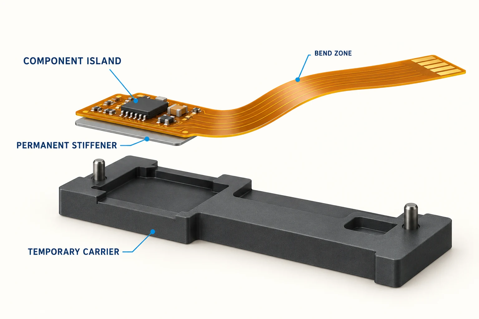
Before fixing the carrier and assembly sequence, review the flexible PCB stiffener requirements for permanent support and connector fit.
Review the printing and placement plan with the assembler
Thin flexible circuits need an agreed support and registration strategy during solder paste printing and component placement. Ask the assembler to explain how it establishes a stable working surface and how the process accommodates local thickness changes. Review the circuit, carrier and stencil together rather than treating the carrier as an afterthought.
Placement information should show polarity, orientation and component-side conventions clearly. Define whether the supplier may adjust the panel layout or placement program and what review is required. If the build uses components on both sides, discuss how the first assembled side is supported and protected during the next operation.
Identify the features that deserve a first-article check before the rest of the lot runs. These may include connector position, exposed contact clearance, a crowded island or the location of a supported transition. An early documented check can reveal a file interpretation problem while the affected quantity is still limited.
Confirm material and thermal handling instructions
An assembly process must accommodate the actual circuit construction and the components being attached. Review the dielectric, adhesive, coverlay, stiffener bond and surface finish as a combined structure. A general description such as polyimide does not define every material in the circuit or qualify an unrestricted thermal process.
Ask for a project-specific thermal process review using the relevant material and component supplier instructions. Confirm handling requirements for incoming circuits and components, storage conditions, allowable exposure and any conditioning procedure. Avoid imposing a generic baking temperature or reflow profile without checking compatibility with all affected materials.
The flexible PCB materials guide helps organize the stack-up discussion. Published material properties are useful inputs, but the finished assembly still needs an agreed process and acceptance basis. Record any proposed change to the construction before relying on results from the earlier build.
Protect connectors, contacts and exposed tails
Connector fit should be reviewed with the exact mating part and its current drawing. Confirm contact orientation, tail thickness, insertion depth, alignment and access to the latch. A stiffener that supports insertion should not obstruct the required movement or create an unintended bend at the connector exit.
The handling plan should protect exposed contacts from contamination and mechanical damage. Ask how operators lift the circuit, release it from a carrier and move it into packaging. Define what is acceptable at delicate edges or contact areas rather than leaving the disposition to an informal visual judgement.
Consider the final product assembly station as part of the interface review. An accessible connector on an open bench can become awkward after a shield or housing is installed. Trial the intended sequence with representative parts and record the route, support points and tools required to achieve consistent installation.
Define inspection criteria before evaluating appearance
Agree the inspection standard, applicable edition, class or other contractual criteria before production. Distinguish bare-circuit requirements from soldered assembly requirements and from OEM-specific drawing notes. A general statement that the parts meet IPC does not identify the actual acceptance basis or every customer requirement.
Identify critical characteristics and the method used to evaluate them. Component orientation and visible solder joints may be accessible optically, while other features may need additional inspection agreed with the supplier. Where a method is proposed, confirm what it can detect and what remains outside its coverage.
Require a documented response for nonconformities. A deviation approved for one prototype lot should name the affected revision, quantity and limitation; it should not silently become the standard for future orders. Inspection records should make it possible to connect the accepted parts to the relevant build and release decision.
Distinguish bare-board, assembled and installed tests
Bare-circuit continuity and isolation testing checks specified connectivity before or separately from population. Assembly-level testing can address component placement, connections and circuit operation according to a defined procedure. Installed validation asks whether the assembly performs in the product under the intended mechanical and environmental conditions.
These tests answer different questions. A passed bare-board test does not prove solder joint quality, correct component function or repeated-flex performance. A functional check at room conditions does not establish reliability across an operating envelope that was never tested. State the conditions and limits beside the result.
Agree who supplies the test fixture, software, mating hardware and acceptance thresholds. Define how failures are reported, retested and linked to sample identifiers. If only inspection is included in the quoted assembly scope, make the remaining functional validation responsibility explicit before comparing it with another quotation.
Use a first-article acceptance checklist
A first article should connect the released files to observed build results. Review the file revision, component identities, orientation, local reinforcement, connector fit and relevant test results. Record any departure from the intended production construction so the approval does not imply evidence that the sample cannot provide.
Plan sample quantities and checks through the flexible PCB prototype validation guide. Retain reference samples when they are useful for later comparison. Allocate separate samples where a destructive test or prior conditioning could influence another result.
The checklist below is an example of evidence categories rather than a universal test plan. The responsible engineering and quality teams should choose the methods, sampling and pass limits for the application.
| Review item | Evidence to agree | Decision owner |
|---|---|---|
| Files and BOM | Released revision and approved alternatives | Engineering |
| Support and fit | Stiffener, connector and installation check | Mechanical engineering |
| Assembly quality | Inspection records against agreed criteria | Quality |
| Electrical function | Procedure, limits and identified results | Electronics engineering |
| Delivery readiness | Packaging, records and closed deviations | Quality and purchasing |
Compare quotations on the same assembly scope
Compare the included deliverables before comparing the total price. Check bare-circuit fabrication, component sourcing, carrier and stencil charges, assembly operations, inspection, test development and packaging. Separate one-time engineering or tooling costs from recurring unit costs so a prototype quote can be compared with a later repeat order.
Review assumptions about quantity, component availability, usable customer-supplied material and yield-related allowances. Ask which changes trigger a revised quotation. An attractive unit price can be difficult to interpret when component procurement or a necessary test fixture is excluded.
Use the flexible PCB cost review guide for the broader quotation discussion. For assembly, add a responsibility matrix and a list of unresolved items. Purchasing can then compare offers against a common package rather than treating different scopes as interchangeable.
Plan changes, rework and production transfer
Define approval requirements for BOM substitutions, material changes, carrier modifications and process changes that could affect the assembly. Keep the circuit and assembly revisions linked. An outline change can affect the support tool even when the component list stays the same, while a replacement connector can affect the installation trial.
Agree permitted rework and the evidence needed after it. Do not assume a repaired assembly remains equivalent to an untouched sample for every validation purpose. Identify the affected units, retain their history and obtain the responsible approval where the application requires it.
Before shipment, confirm how each assembly is identified and protected against uncontrolled folding or contact damage. Packaging should support the shape required for transport without forcing a new bend into a critical area. Agree the labels, lot references and inspection documents that receiving personnel need to reconcile the shipment with the purchase order. If assemblies are delivered on a carrier, specify who removes it and how that operation is performed.
The FPC manufacturing process guide describes the preceding fabrication checkpoints. Carry the approved drawing, stack-up, BOM, assembly instructions and test requirements through the handoff. A repeat order should reference this controlled package, not an earlier quotation with open questions.
Example: investigate a display assembly installation problem
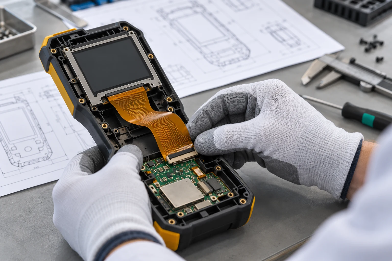
Consider an illustrative compact instrument with a populated FPC island and a tail connecting its display. The module functions outside the housing, but installation places a twist near the connector and pushes the tail against a rib. The team should identify the installed geometry and handling sequence before deciding whether the issue is caused by fabrication, placement or mechanical integration.
Mechanical engineering can document the route and connector access, while the assembler reviews support, stiffener position and unloading method. Quality should link observations to identified samples and distinguish a damaged handling specimen from a representative build. Purchasing coordinates the revised scope instead of requesting an undefined more reliable assembly.
The next first article should check the accepted changes in the actual housing revision and repeat the relevant functional tests. Photograph the route and document remaining limits. This example is a decision framework, not a reported Teleconix customer case, a lifetime demonstration or evidence for a universal bend rule.
Related Products
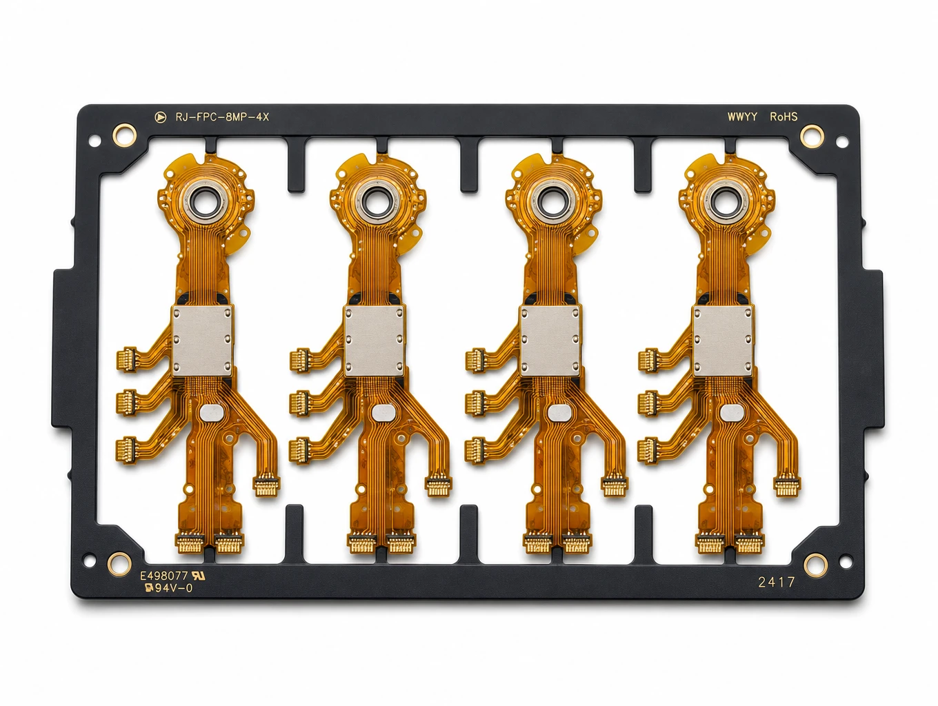
Multi-Branch Humanoid Robotic Joint FPC
Model: TLX-ROB-JNT01
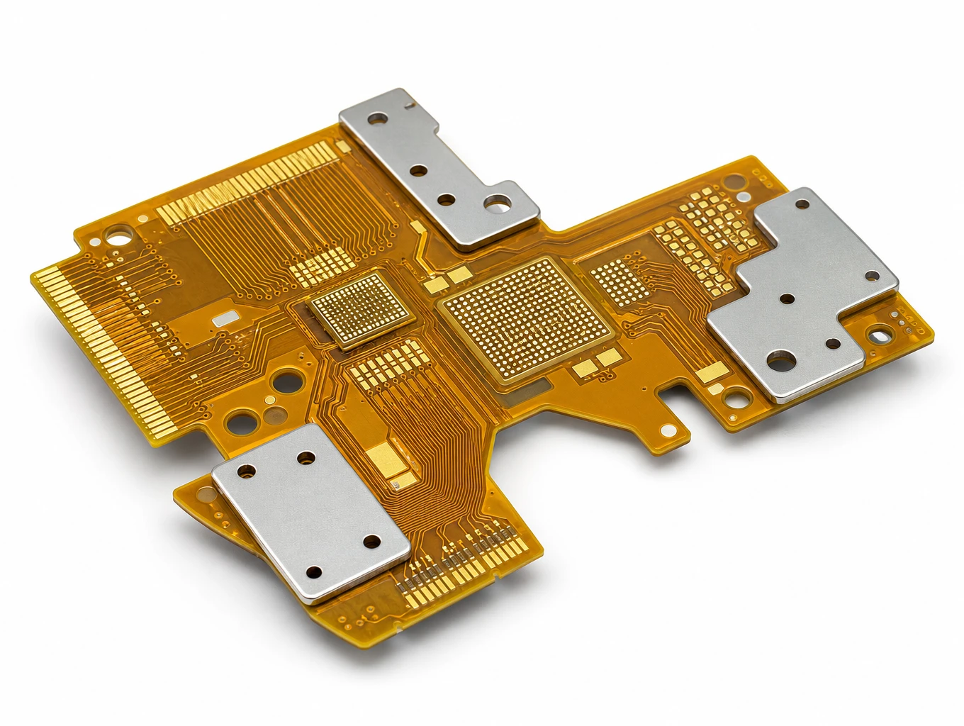
400G/800G High-Speed Optical Transceiver Multi-Layer Flex PCB
Model: TLX-COMM-OPT03
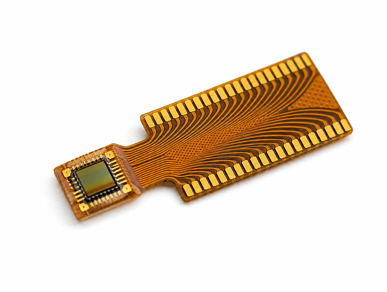
Medical Endoscope Micro-Display FPC
Model: TLX-DFPC-MED06
Related Solutions

AI & Robotics & Special Industrial FPC
Flexible circuits for robotic joints, vision sensors, actuators and industrial interfaces. Match the circuit route to the motion, electrical connections and enclosure of your machine.
Explore Solutions
Display FPC
Display FPC products for OLED, AMOLED, micro-LED and TFT-LCD modules in handheld, wearable, automotive and industrial devices. Review the display interface, connector and installed flex shape together.
Explore Solutions
Smart Automotive Electronics FPC
Automotive FPC products for battery monitoring, ADAS cameras, radar, cockpit displays, steering controls and LED lighting. Select a starting configuration by module function and installation needs.
Explore Solutions AI & Robotics & Special Industrial FPC
Flexible circuits for robotic joints, vision sensors, actuators and industrial interfaces. Match the circuit route to the motion, electrical connections and enclosure of your machine.
Explore Solutions Display FPC
Display FPC products for OLED, AMOLED, micro-LED and TFT-LCD modules in handheld, wearable, automotive and industrial devices. Review the display interface, connector and installed flex shape together.
Explore Solutions Smart Automotive Electronics FPC
Automotive FPC products for battery monitoring, ADAS cameras, radar, cockpit displays, steering controls and LED lighting. Select a starting configuration by module function and installation needs.
Explore SolutionsFrequently Asked Questions
Conclusion: release an assembly scope that can be verified
A useful FPC assembly RFQ defines what is built, how flexible areas are supported and what evidence supports acceptance. Align the fabrication package, BOM, placement information and installed configuration. Separate the supplier’s quoted tests from the OEM’s remaining validation work and close changes through a controlled release.
Use the Teleconix OEM and ODM project workflow to organize the discussion, then share your drawing, BOM, quantities, assembly scope and validation needs through the Teleconix project inquiry form. Ask for confirmation of sourcing, support, inspection, testing and schedule for the actual project before authorizing production.