

Define the role of a humanoid robot FPC before choosing a layout
A humanoid robot FPC is a flexible printed circuit used for a defined connection inside a humanoid platform. Its value depends on the installed task: carrying fingertip sensor signals, linking a compact hand controller, connecting a head module or fitting a controlled route between assemblies. It should be evaluated as part of an electrical and mechanical architecture, rather than selected because the robot has a human-shaped body.
For an OEM team, the first deliverable is an interface map. Identify which electronics sit on each side of the connection, what information or power crosses it and who controls the requirements. A tactile sensor branch and a motor supply branch may share an enclosure while needing very different conductor, protection and verification decisions. A convenient flat shape does not establish that one circuit can serve both roles.
Our robotics FPC motion and sensor guide introduces the broader construction and application questions. This article concentrates on humanoid hand integration, distributed electronics and acceptance responsibilities. Detailed routing through a single moving joint remains a separate design review.
Start with the module boundary
Write a short purpose statement for every proposed flex assembly. For example: connect the approved finger sensor boards to a palm controller through a serviceable hand module. Add the operating states, mating connectors, permitted movement and delivery scope. Record open items explicitly. The circuit supplier can review a proposed construction, but it cannot infer missing sensor timing, actuator loading or robot safety requirements from an outline drawing.
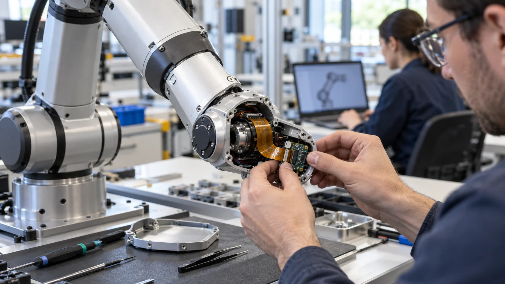
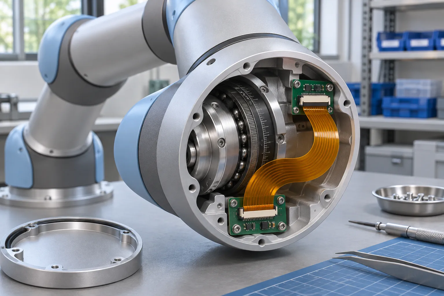
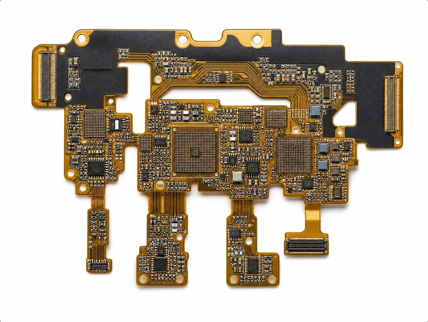
The two illustrations here are engineering concepts generated for explanation. They do not depict a verified Teleconix customer project or establish the construction of a commercial humanoid hand. Actual production geometry and validation must follow the OEM's released documents.
Separate hand, head and body connections into controlled zones
Divide the robot into connection zones before combining circuits. A zone map makes connector ownership, assembly access and test boundaries visible. It also prevents a successful hand prototype from being treated as evidence for a different connection in the torso or head.
| Connection zone | Questions for the OEM | Evidence to release |
|---|---|---|
| Finger and palm sensing | Where are sensor conditioning and local processing located? Which branches move? | Sensor interfaces, installed finger views, assembly and signal checks |
| Hand to wrist module | Where does the module disconnect? Which motion reaches the connection? | Mating definition, service sequence, motion envelope and support details |
| Head electronics | Which camera, display or other modules are actually connected? | Interface requirements, enclosure constraints and relevant electrical verification |
| Torso and distributed control | Which links are appropriate for flex, cable or another interconnect? | System architecture, routing review and allocation of verification responsibility |
Texas Instruments' humanoid robotics communication application note distinguishes motor control, perception, tactile sensing and other communication tasks. It is useful background for separating requirements. It is not evidence that an unspecified FPC supports a particular network protocol, data rate or motor current.
Give each zone a separate interface record
For each zone, record the endpoint names, connector part numbers, pin assignment, reference return paths, proposed construction and mechanical revision. Identify what is fixed during normal operation and what moves during installation, service or every operating cycle. A shared drawing should show the agreed separation between flex branches and any insulated wiring or harness.
Keep the commercial scope equally clear. Bare circuits, populated sensor interconnects and complete qualified hand modules are different deliverables. The OEM and supplier should agree what is included before comparing quotations. Capability discussions can begin through the AI and robotics FPC application page, using the actual module requirements rather than a generic humanoid specification.
Integrate tactile sensing as a complete fingertip and palm assembly
A hand sensor connection must work inside the finished finger, with its covers, supports, actuators and assembly sequence. Begin with the complete stack of parts. Identify sensor placement, contact surfaces, conditioning electronics, flex exits and the physical support available at every transition.

Analog Devices discusses the packaging and integration constraints of tactile technology in its robotics touch sensing article. The useful lesson for an interconnect review is that the sensor, signal conditioning and connectivity all compete for space. Selecting a sensor alone does not resolve how its connection behaves after housing closure or repeated movement.
Review branches individually
A branching finger circuit may reduce separate interconnect pieces, but it can also couple assembly and replacement decisions. Ask whether each finger can be installed without pulling on adjacent branches. Check whether a damaged module can be replaced at the intended service boundary. If the answer requires bending or peeling a branch outside its approved route, revise the assembly or module architecture.
Record how the circuit is supported near a sensor board and where the support ends. Show nearby screw bosses, adhesive areas and potential contact surfaces. A mechanical clamp must not be assumed to be an electrical ground, and an adhesive used for positioning must not be assumed suitable for the complete operating environment.
Keep calibration responsibilities explicit. Sensor placement, mechanical preload and an assembled cover may influence the system response. The OEM should define the calibration procedure, acceptable variation and any recalibration needed after module replacement. A continuity report for the bare FPC does not establish tactile measurement accuracy.
Allocate signal interfaces and local processing responsibilities
Freeze the electrical role of each branch before optimizing its shape. List the actual sensor interface, power rails, return conductors and connector assignment. Mark which requirements are already specified by a component manufacturer and which must be derived by the platform designer.
Infineon's dexterous hand application overview describes hand-level coordination of sensing, feedback and motor nodes. It illustrates why an OEM may distribute control within the hand. It does not prescribe one universal flex topology; the controller locations and communication architecture remain platform decisions.
Place decisions with their actual owners
The system electronics team should define signal types, loading assumptions, timing and any controlled-impedance requirements. The mechanical team owns installed space and movement. The circuit supplier reviews fabrication assumptions, proposed stack-up and documented acceptance criteria. The assembly supplier must know which components, connectors and joining operations belong in its delivery.
Where the proposed assembly includes high-speed signals, agree the relevant channel definition and evidence. A fabrication impedance coupon addresses its specified construction and test method; it is not automatically a complete assessment of connector transitions or an installed sensor channel. For low-level signals, the OEM should specify relevant noise and measurement conditions instead of substituting an unrelated high-speed requirement.
Separate actuator supply and sensor requirements in the review. Conductor sizing, heat, protection and electrical noise depend on the actual loads and layout. Do not transfer a current claim from an unrelated circuit to a narrow hand sensor tail. Record any decision to keep motor supply wiring separate, along with the routing and return-path implications for the sensor connection.
For a populated interconnect, use the flexible PCB assembly guide to prepare the additional component and assembly information. Check that the proposed bill of materials and placement files match the circuit revision under discussion.
Review coupled poses and service movement across the complete hand
Validate the installed movement envelope, not a single open-hand pose. A hand may combine finger articulation, wrist movement and local branch deformation. Even when each joint has an acceptable nominal route, their combined positions can change clearances and load the shared palm connection.
Build a pose matrix with the mechanical team. Include relevant operating positions, transitions, housing closure and service access. Name the fixture and the approved sequence so that repeated checks use the same conditions. Avoid a vague instruction to test through full movement when the robot can reach many different combinations of positions.
Separate fixed, moving and handled regions
Mark static installation folds separately from recurring movement. Also identify parts that move during cover removal, connector replacement or finger-module service. A section that remains still during operation can still be damaged by an uncontrolled assembly or maintenance step. Show the supported span and the intended free span in the same installed view.
For the detailed geometry around an articulated connection, refer to our robot joint FPC routing and integration guide. Record the local support, bend path and potential interference there, then bring the results back into the full hand pose matrix. The purpose is to connect local and system evidence, not repeat a bend rule across every humanoid connection.
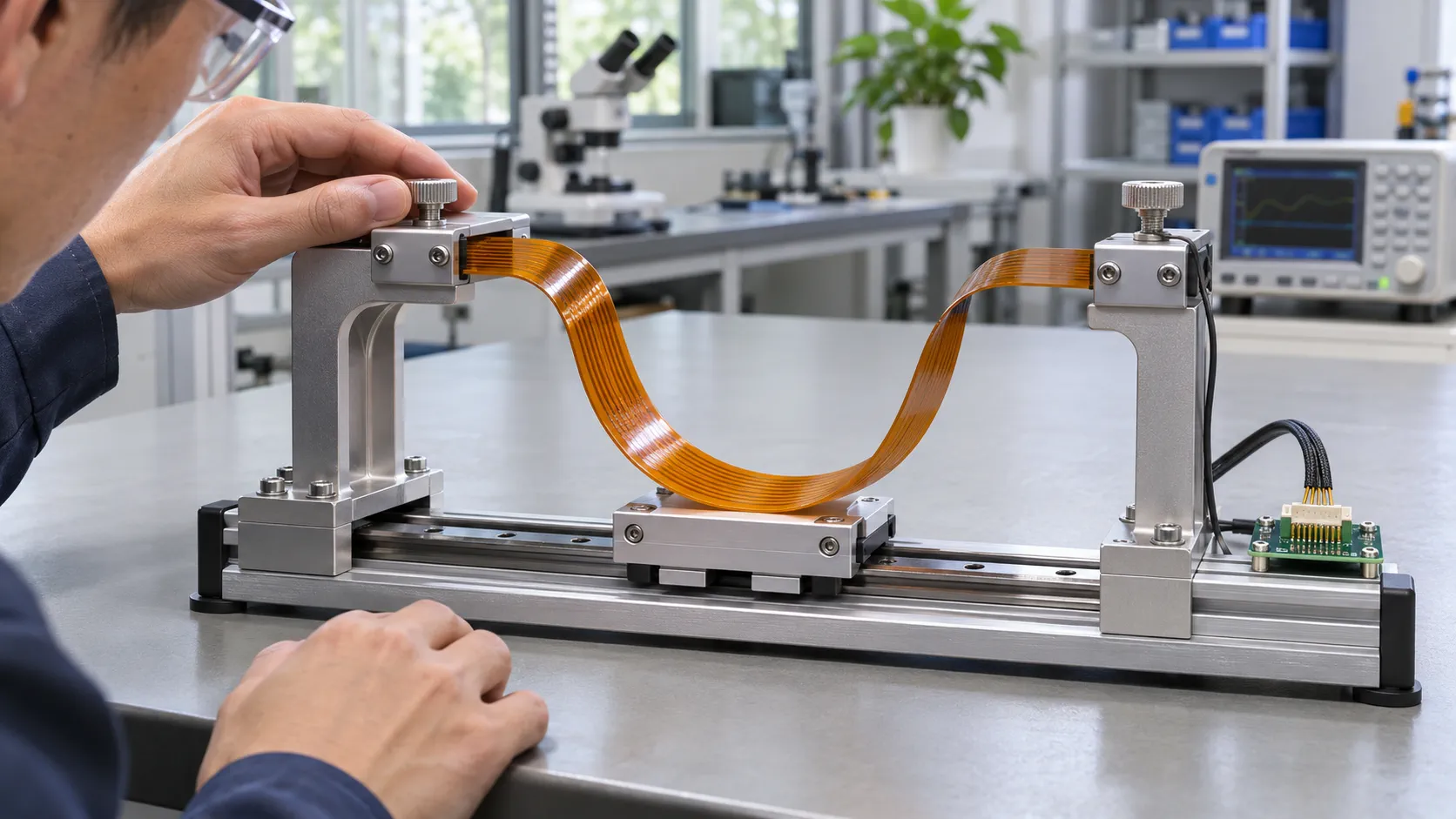
The OEM should define the required life and failure criteria for its application. Our flex PCB fatigue testing guide explains the inputs needed for a controlled validation plan. Material choice alone does not guarantee service life. Movement, geometry, fixtures, environment and inspection criteria must remain linked to the tested revision.
Run powered movement checks only under an approved safe test procedure with the responsible robot team. Specify the representative actuation states needed to assess sensing behaviour. An interconnect supplier's inspection does not replace the platform owner's functional or safety verification.
Make connector, assembly and replacement boundaries reviewable
A modular hand needs a deliberate disconnection and replacement strategy. Decide which interface the technician can access, which part is replaced and which components remain untouched. Then check that the physical assembly sequence follows that strategy without applying tension to the flex.
Identify every mating pair with part number, orientation and locking operation. For a flex-tail connector, confirm the required finished mating thickness and the applicable contact-side orientation from the connector documentation. Include any stiffener and adhesive construction in the review. Do not infer the mating thickness from the base film or a nominal circuit thickness alone.
Support the interface without moving the problem
A stiffener can support a connector region while shifting the transition to an adjacent free span. Review both together. Our flex PCB stiffener guide provides a starting point for documenting support areas and assembly interfaces. The hand drawing should still show the specific stiffener boundary, nearby components and route to the next restraint.
For dense palm electronics, check access after all other parts are installed. A connector that is easy to mate on an open bench may be inaccessible behind a motor bracket or housing wall. Record the intended tool access, cable restraint and inspection method. If the supplier cannot see or verify the latch after assembly, agree a suitable alternative check with the OEM.
Consider mistake prevention at the module level. Similar connectors and finger branches need clear identification in the approved assembly documents. Use appropriate marking or other controls that fit the construction. Any proposed marking must remain legible and suitable for the handling and environment; do not assume that a label fixes an ambiguous assembly route.
Replacement instructions should state whether calibration, signal verification or another acceptance step is required after work. These are system requirements to agree with the OEM, rather than promises that a new flex circuit can be exchanged without further checks.
Validate the circuit, hand module and robot as separate stages
Use staged acceptance so that a pass at one level has a clear meaning. Bare-circuit testing checks the agreed circuit requirements. Module testing adds connectors, sensors, assembly and local movement. Integration testing evaluates the connection in the robot under the approved operating conditions.
| Stage | Typical review scope | Required record |
|---|---|---|
| Fabricated circuit | Construction, outline, inspected features and specified electrical checks | Circuit revision, agreed inspection method and results |
| Assembled hand module | Mating, branch support, sensor communication and defined local movement | Assembly revision, fixture, software or configuration reference and anomalies |
| Integrated humanoid platform | Coupled poses, representative actuation, sensing behaviour and service access | Approved system procedure, acceptance criteria and accountable owner |
Use the flex PCB electrical testing guide when defining fabrication and interconnect checks. Make clear which tests are included in the supplier's report and which require the customer's electronics, firmware or integrated fixture. A statement such as electrically tested is too broad to establish sensor function or operating reliability.
Capture a baseline before introducing variables
At module level, record the initial assembly condition and sensor response under the defined setup. Repeat the agreed checks after housing closure and the relevant movement sequence. Document connector seating, clearances and any change in communication or sensing response. Use the same revision and configuration references so that the comparison is meaningful.
Define how failures are classified. An intermittent reading might involve the sensor, software, connector, circuit or mechanical loading. Preserve the observed operating state before replacing parts. The investigation should distinguish evidence from assumptions; a communication failure does not by itself establish a cracked conductor.
The OEM must set sample quantities, acceptance limits and approval gates appropriate to its risk and production plan. Avoid approving a production order solely because one engineering demonstration worked. Any deviation, rework or alternate material used during the demonstration needs a documented disposition before the next build.
Release a controlled humanoid robot FPC RFQ and approval package
A useful quotation package links the proposed humanoid robot FPC to an identified hand or other module. It should enable suppliers to explain construction assumptions, open questions and included verification without guessing the robot architecture.
- Circuit definition: revision-controlled circuit data, outline, drilling information, proposed stack-up, finish and relevant fabrication notes.
- Installed mechanics: enclosure views, branch identification, connector orientation, supported and moving regions, pose matrix and service access.
- Electrical interfaces: endpoint and pin assignment, signal and power roles, return paths and any specified impedance or other electrical acceptance requirements.
- Assembly scope: approved BOM, placement and assembly drawings when populated delivery is requested, including connector and sensor documents.
- Verification plan: separate circuit, module and system checks, approved fixtures and procedures, report requirements and responsibility for open decisions.
- Commercial stages: prototype and later quantities, approved revision, expected delivery scope and the evidence needed before moving to the next order.
The flexible PCB RFQ checklist can help structure the common fabrication documents. Add the humanoid-specific interface map and hand acceptance responsibilities rather than replacing the common package with a product photograph.
Compare scope before comparing price
Ask each supplier to state exclusions and assumptions. One proposal may cover a bare circuit while another includes assembly and a dedicated test fixture. Confirm whether tooling, test development, alternate materials and revision changes are addressed. None of these should remain an implied part of a single unit price.
Before release, close or assign every open item with an owner and an approval point. Retain the evidence for the exact revision being ordered. When the hand architecture changes, review the affected circuit, assembly and verification documents together. This controlled handoff gives the next build a more reliable basis than a layout that fits only the first demonstration enclosure.
Related Products
Multi-Branch Humanoid Robotic Joint FPC
Model: TLX-ROB-JNT01
High-Speed AI Vision & LiDAR Sensor Matrix FPC
Model: TLX-AI-VIS02
Related Solutions

AI & Robotics & Special Industrial FPC
Flexible circuits for robotic joints, vision sensors, actuators and industrial interfaces. Match the circuit route to the motion, electrical connections and enclosure of your machine.
Explore Solutions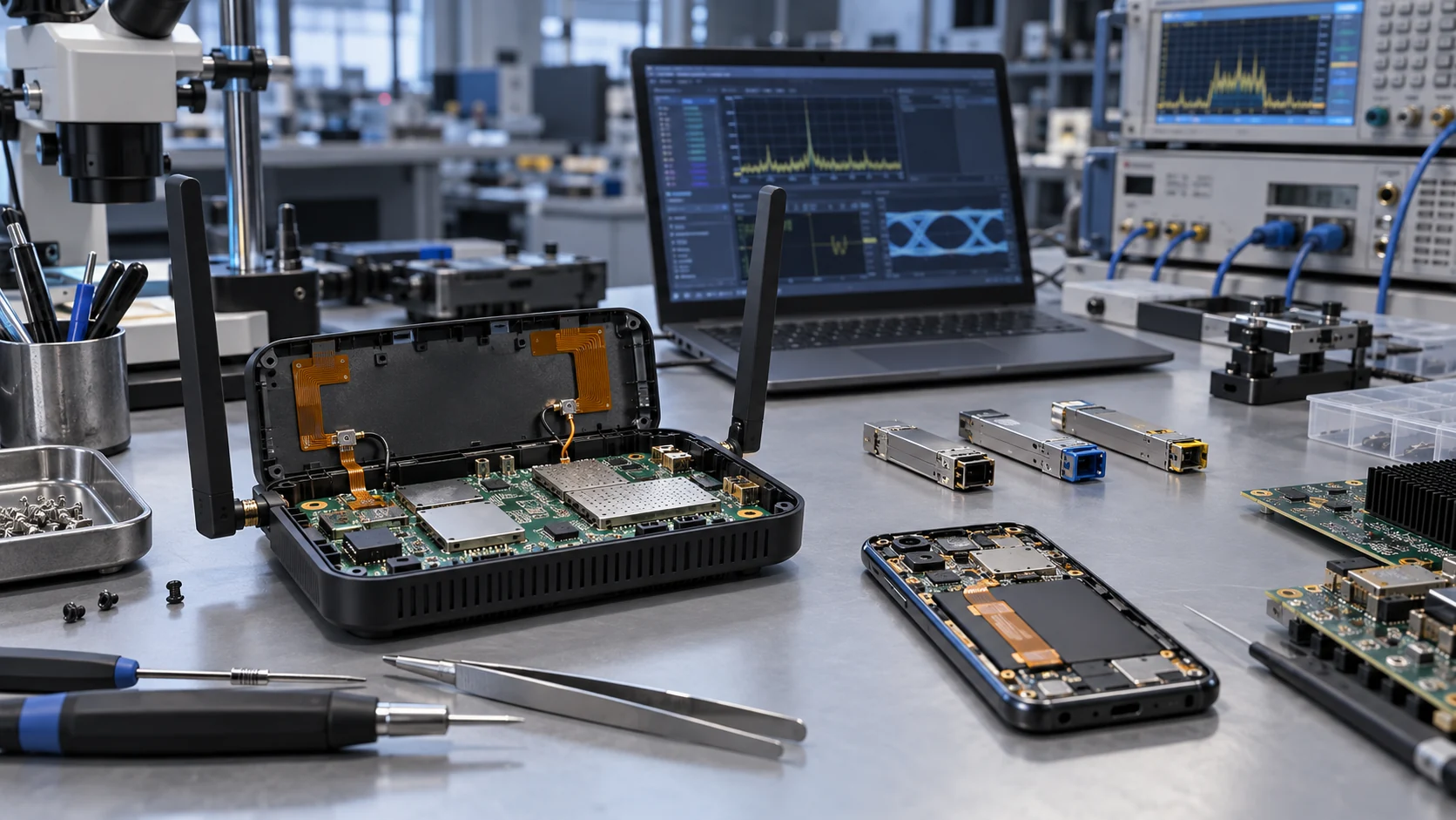
RF & Communication FPC Solutions
Custom RF flexible PCB and telecom interconnects for antenna modules, wireless terminals and high-speed communication assemblies. Coordinate materials, signal paths, shielding and connector support with Teleconix before prototype release.
Explore Solutions AI & Robotics & Special Industrial FPC
Flexible circuits for robotic joints, vision sensors, actuators and industrial interfaces. Match the circuit route to the motion, electrical connections and enclosure of your machine.
Explore Solutions RF & Communication FPC Solutions
Custom RF flexible PCB and telecom interconnects for antenna modules, wireless terminals and high-speed communication assemblies. Coordinate materials, signal paths, shielding and connector support with Teleconix before prototype release.
Explore SolutionsFrequently Asked Questions
Conclusion: release an agreed humanoid hand interconnect
A humanoid robot FPC should have a defined place in the robot architecture, an agreed hand or module boundary and evidence tied to its installed use. Separate tactile sensing, local control and actuator wiring requirements; then validate the circuit, assembled module and integrated platform at their respective stages.
Share your interface map, mechanical views, proposed circuit data and prototype acceptance requirements with Teleconix. Discuss your humanoid robot FPC project so that construction, assembly scope and remaining engineering decisions can be reviewed before an OEM order is released.