
Introduction
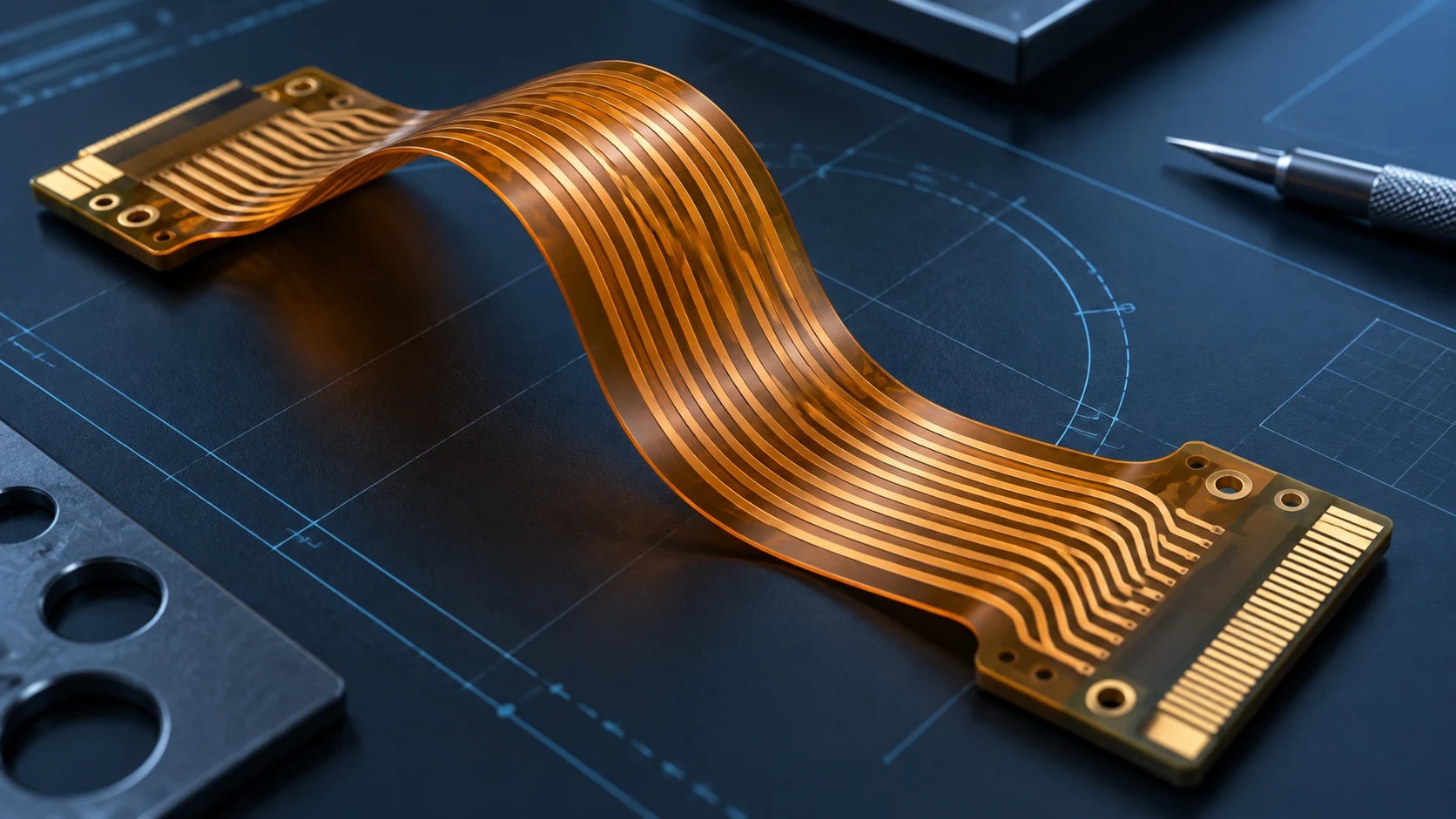
What is a flexible PCB? It is a printed circuit built on a thin, bendable dielectric film so conductors can route electrical power and signals through spaces that a rigid board or separate wire harness may not fit. The terms flexible printed circuit, flex circuit, FPC and flex PCB are often used for the same family of interconnects.
For an OEM team, the definition is only the starting point. A useful FPC specification must connect the circuit to the installed shape, number of bends, connector interfaces, materials, assembly process and required lifetime. A circuit that bends once during installation needs a different design review from one that moves through thousands or millions of cycles.
This guide explains flexible circuit construction, common types, the difference between FPC, FFC and rigid-flex, and the information a supplier needs before quotation. It is written for engineering, quality and purchasing teams that need a shared definition before comparing suppliers. For detailed layout rules, continue with the flexible PCB design guidelines.
What is a flexible PCB?
A flexible PCB is an electrical interconnect whose copper conductors are patterned on one or more flexible dielectric layers. Polyimide is widely used as the base dielectric, while other films and adhesive systems may be selected for a specific construction. A protective coverlay normally insulates the conductors while openings expose pads, contacts or component areas.
The circuit may be supplied as a bare flex, an assembled flexible circuit, or part of a rigid-flex board. It can carry signals, distribute power, connect sensors and displays, or replace a group of discrete wires. Its value comes from combining electrical routing with a repeatable three-dimensional form.
“Flexible” does not mean every part should bend freely. Connector ends, component areas, plated holes and local transitions often need support. The intended bend zone, formed shape and supported areas should be defined on the drawing instead of left to the assembler to infer.
What does FPC mean in electronics?
FPC usually means flexible printed circuit. In purchasing conversations it may describe a bare flexible circuit or an assembled flexible PCB, so the scope should be stated clearly. If components, connectors, shielding or pressure-sensitive adhesive are required, list them as separate deliverables.
The plural “FPCs” simply refers to multiple flexible circuits. However, an FPC is not automatically equivalent to a flexible flat cable. Both can be thin and flexible, but their conductor formation, termination options and design freedom differ. Using precise names prevents the wrong construction from entering a quotation.
OEM documentation should use one term consistently and define the finished part in the drawing and BOM. A supplier should not have to decide whether “FPC” means a bare circuit, a populated assembly or a complete cable set.
How a flexible PCB is constructed
A basic single-sided FPC contains a flexible base film, a patterned copper conductor layer and a protective coverlay. Adhesive may bond these layers, while adhesive-free laminates are also available. Pads and contacts remain exposed through designed openings. Stiffeners can be bonded under connector fingers, components or other areas that need controlled thickness and support.
Double-sided and multilayer flex add conductor layers, dielectric layers and interconnections. Vias or plated through holes may connect layers, but their position relative to a bend requires review. Shielding films, selective plating, local reinforcement and pressure-sensitive adhesive can add function while also changing thickness and flexibility.
Each additional material changes the stack-up. The flexible PCB materials and stack-up guide explains how copper type, dielectric, adhesive, coverlay and stiffeners should be documented for an RFQ.
How a flex circuit carries signals and power
The copper traces on an FPC perform the same electrical task as traces on a rigid PCB: they connect pads, contacts, components and connectors according to the released netlist. The flexible substrate changes the mechanical environment, not the basic need to control conductor width, spacing, return paths, current capacity and signal integrity.
High-speed or sensitive signals may require controlled impedance, reference planes, shielding and a stable installed geometry. Power paths may need wider copper features and thermal review. Tight bends, repeated movement and local thickness transitions can affect mechanical reliability even when the electrical design is correct.
Engineering teams should therefore review electrical and mechanical requirements together. A trace should not be routed through a bend merely because it fits in the two-dimensional artwork. Its direction, width, copper type, neutral-axis position and support all influence the final design.
Common types of flexible PCBs
Flexible PCBs are commonly grouped by layer count and construction. Single-sided flex uses one conductor layer and suits many simple tails, switches and sensor connections. Double-sided flex adds routing density and interlayer connections. Multilayer flex supports more complex circuits but increases stack-up thickness and design constraints.
Some projects use sculptured or selectively reinforced features, while others combine flexible and rigid sections in one rigid-flex structure. The correct type depends on routing density, connector strategy, assembly, bend duty, available space and production requirements.
The lowest layer count is often attractive, but simplification should not create difficult routing, weak reference paths or excessive interconnect transitions. The OEM and supplier should review the complete installed system rather than choosing a construction from a short label alone.
Single-sided, double-sided and multilayer FPCs
A single-sided circuit offers the thinnest and simplest routing structure when one copper layer can satisfy the design. It can fold or form around an assembly and may include local stiffeners. Component attachment and exposed contacts are possible where the coverlay is opened.
A double-sided circuit allows connections on both sides and can use plated features to join them. It gives the designer more routing freedom but introduces registration, plating and bend-zone considerations. Plated holes and abrupt layer changes should be kept away from active bends unless the design has been specifically engineered and validated.
Multilayer FPCs provide higher density, reference layers or more complex interconnects. They are also thicker and less flexible than a comparable single-layer circuit. If only part of the circuit needs multiple layers, a localized construction or rigid-flex architecture may be worth evaluating with the manufacturer.
FPC vs FFC: what is the difference?
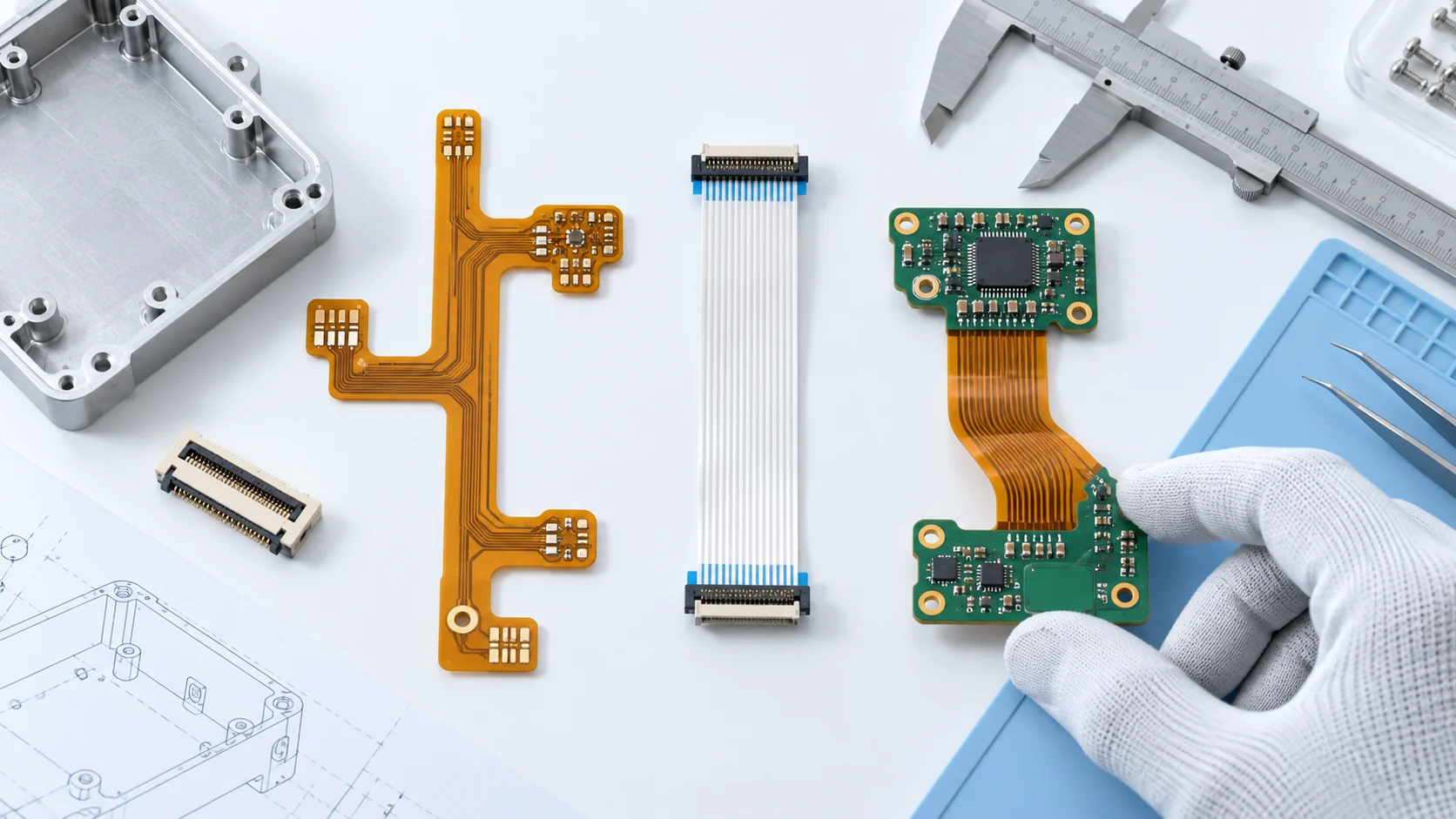
An FPC uses etched or otherwise patterned copper conductors on a flexible dielectric, which allows traces to change direction, vary in width and connect to pads, vias and components. A flexible flat cable, or FFC, usually consists of parallel flat conductors laminated between insulating films. It is commonly used as a simple point-to-point connection.
FFC can be efficient when the conductor pitch, straight routing and compatible connectors meet the requirement. FPC is more suitable when the circuit needs shaped outlines, branching paths, components, local reinforcement, custom contact geometry or more complex electrical routing.
The choice should be based on the interface and assembly, not appearance. Define conductor count, pitch, current, length, folding, mating connector, insertion cycles and environmental needs. Then compare whether a standard FFC or a custom FPC provides the more controlled solution.
For an OEM comparison of connector fit, installed routing, movement and full assembly cost, use the FPC vs FFC interconnect selection guide before choosing a cable or custom circuit.
FPC vs rigid PCB
A rigid PCB holds components and conductors on a dimensionally stable board. An FPC routes through constrained or moving spaces and can replace connectors, cables or multiple rigid boards in some assemblies. The two are complementary technologies rather than universal substitutes.
Rigid boards generally provide stronger support for large components and connectors. Flexible circuits can reduce interconnect bulk and help an assembly follow a product enclosure. They also require bend-aware routing, handling controls and local support where forces enter the circuit.
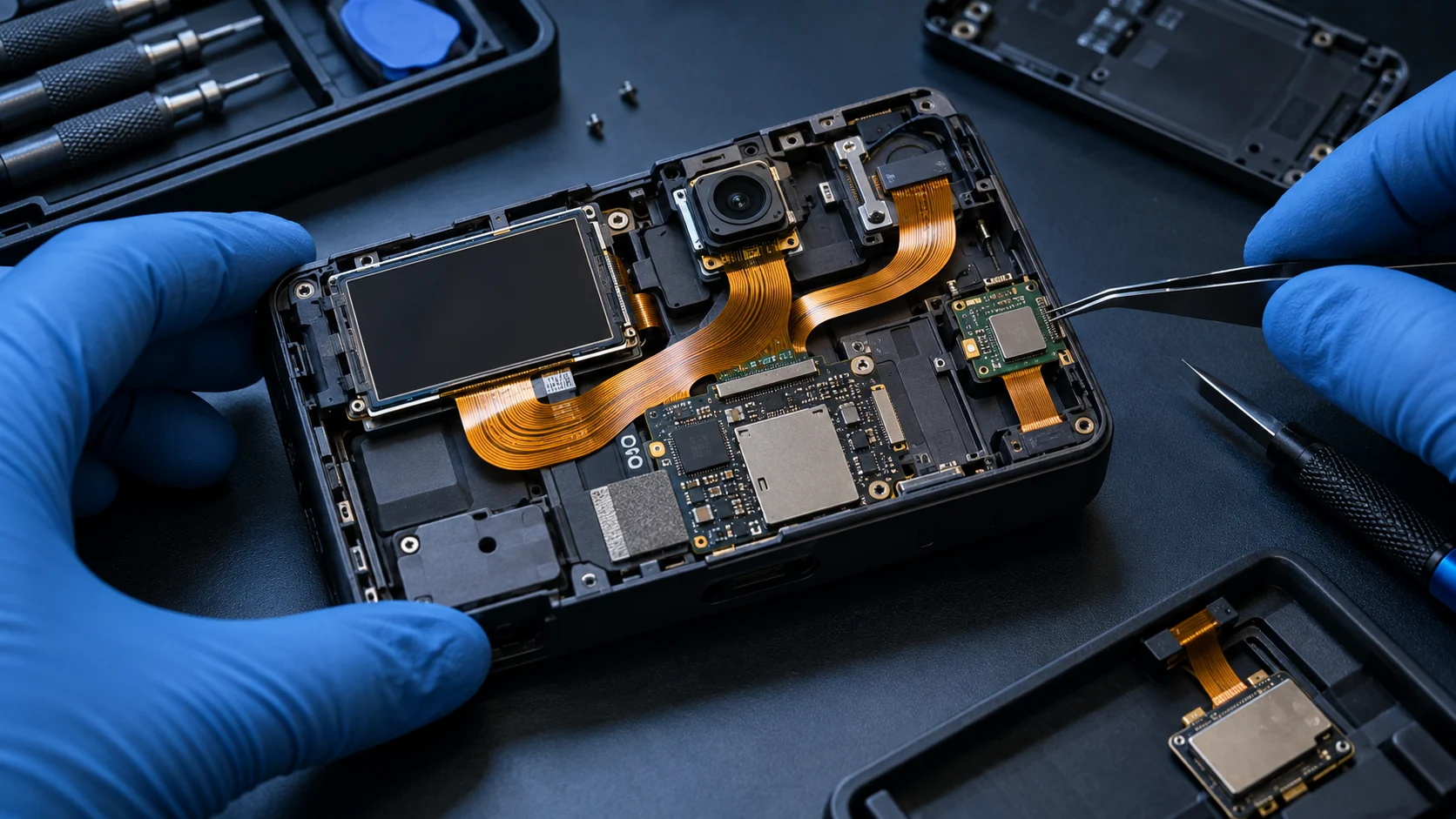
Many products use both: a rigid main board for processing and power, plus FPC tails for cameras, sensors, displays, controls or batteries. The interface between them should be reviewed for connector retention, strain relief, installation sequence and serviceability.
FPC vs rigid-flex PCB
A rigid-flex PCB integrates rigid board sections and flexible layers into one manufactured structure. Components can be mounted on the rigid sections while the flexible sections form the interconnect. A separate FPC solution uses individual flex circuits joined to rigid boards or other devices through connectors, soldering or bonding.
Rigid-flex can reduce connector count and create a compact integrated assembly. It also requires coordinated stack-up design, fabrication and assembly from the beginning. Separate FPCs can provide modularity, replacement options and independent sourcing, but every interface adds space and a potential failure point.
Compare the full system: board count, connectors, assembly labor, service strategy, test access, volume and reliability requirements. A lower piece price for one component does not necessarily produce the lower total assembly cost.
For the next design and purchasing decisions, use the rigid flex PCB OEM design and sourcing checklist to compare integrated rigid-flex with supported flex, define regional constructions and prepare an RFQ with clear acceptance evidence.
Static flex and dynamic flex applications
Static flex usually means the circuit is bent or formed during installation and then remains in place. Dynamic flex means the circuit repeatedly moves during product operation. These labels must be followed by real conditions: bend radius, angle, direction, cycle count, speed, temperature and any twist or tensile load.
A design suitable for one installation fold may not survive continuous motion. Dynamic applications need careful control of copper type, trace direction, layer count, stack-up symmetry and mechanical support. The flex PCB bend radius guide shows how OEM teams can document these conditions before layout release.
Avoid specifying only “flexible” or “millions of cycles.” Give the supplier a testable motion profile and identify the critical bend zone. Prototype validation should reproduce the installed routing, clamps and connectors because these features determine where strain actually occurs.
Where flexible PCBs are used
Flexible circuits are used where space, weight, motion or assembly routing makes a rigid interconnect difficult. Typical examples include display modules, camera systems, medical instruments, automotive electronics, industrial controls, robotics, wearables, battery systems and compact consumer devices.
In a display, an FPC can connect the panel to a controller within a thin enclosure. In a camera or endoscope, it can route signals through a narrow body. In a robotic joint, it may follow controlled motion. In each case, the application changes the stack-up, shielding, bend and test requirements.
Use the application to drive the specification. State where the circuit is clamped, how it is installed, which surfaces can contact nearby parts and whether technicians will handle it during service. A simple three-dimensional sketch can reveal risks that are invisible in the Gerber files.
Benefits and design tradeoffs
FPCs can reduce interconnect volume, support repeated assembly geometry, eliminate some wiring steps and fit complex enclosures. A printed pattern can also provide more consistent conductor placement than a manually routed wire bundle. These benefits are strongest when the flex is designed as part of the product architecture.
The tradeoffs include sensitivity to bend design, handling and unsupported mechanical loads. Dense multilayer constructions become less flexible. Local reinforcements, shielding and connectors add thickness. Custom tooling, test fixtures and material choices can affect lead time and cost.
Weight and space savings should be measured in the complete assembly. A flex may remove a wire bundle and several connectors, but it can also require a supported routing path, dedicated installation tools or additional inspection. Early collaboration among electrical, mechanical, manufacturing and sourcing teams usually produces a more realistic comparison than selecting the interconnect after the enclosure is fixed.
An OEM should judge value at system level. Compare connector count, assembly time, enclosure space, serviceability, validation effort and expected volume. A well-defined FPC can simplify the product, while an undefined one can move uncertainty from the wire harness into the circuit drawing.
What OEM buyers should define before an RFQ
Begin with controlled design data and a dimensioned drawing. Define layer count, finished thickness, materials or acceptable equivalents, copper, coverlay, surface finish, stiffeners, connectors, exposed contacts and critical tolerances. Mark bend zones, installed shape and areas that must remain flat.
Add electrical requirements, impedance where applicable, test coverage, quantities, panel or delivery format, assembly scope and required records. State whether the supplier should quote a bare FPC, components assembled, or a complete tested module. Identify the released revision in every file.
For early concepts, an annotated mechanical model and interface list can support a manufacturability discussion before final artwork. Teleconix's OEM and ODM project workflow can be used to organize the handoff. For a formal quotation, send one controlled package so every bidder prices the same requirement.
How to review materials, stack-up and bend zones
Review the stack-up from the bend inward. Identify how many copper and dielectric layers cross the bend, where stiffeners and coverlay edges stop, and whether a plated feature or component sits near the transition. Define the installed bend radius and whether the bend is static or dynamic.
Material review should compare thickness, copper type, bonding system, temperature exposure, shielding and assembly compatibility. An equivalent material is acceptable only when the OEM and supplier agree which properties must remain equivalent. Record substitutions before prototype approval.
Trace routing should flow smoothly through the bend where possible. Abrupt width changes, sharp corners, stacked transitions and unsupported connector loads deserve extra attention. Design rules are application-dependent, so use them as a review framework and validate the actual construction.
How manufacturing and quality fit into procurement
Once the design is defined, the supplier converts it into a controlled manufacturing route. Imaging, etching, drilling, plating, lamination, coverlay, finishing, profiling and electrical test are selected according to the stack-up. The FPC manufacturing process guide explains the checkpoints an OEM can connect to the released drawing.
Quality requirements should name evidence, not rely on generic claims. Define critical dimensions, electrical test coverage, appearance criteria, material traceability and any first article or lot records. Agree how deviations and substitutions are approved.
Quotation review should separate recurring part price from tooling, testing, documentation and assembly charges. The flexible PCB cost guide helps purchasing teams compare quotations on the same scope instead of selecting a low price that omits required operations.
Prototype, validate and release production
A prototype should confirm fit, electrical function, assembly handling and the installed bend. Inspect connector engagement, local support and clearance around moving parts. If the application is dynamic, use a test fixture that reproduces the real radius, angle, speed and restraint conditions.
Record the approved drawing, stack-up, sample results and open deviations. When a design change follows testing, update the controlled files instead of relying on a verbal instruction. The production supplier should acknowledge the final revision and any approved equivalent materials.
Validation should also include the next manufacturing step. Confirm that operators can install the circuit without creasing it, that soldering or connector insertion does not overload the tail, and that inspection points remain accessible. If the circuit is shipped as an assembly, verify packaging and transport in the form in which the production line will receive it.
Before volume release, confirm delivery format, inspection records, change notification and nonconformance handling. This turns “what is a flexible PCB?” into a practical procurement definition: a specific electrical and mechanical interconnect that can be built, tested and repeated against one agreed baseline.
Related Products
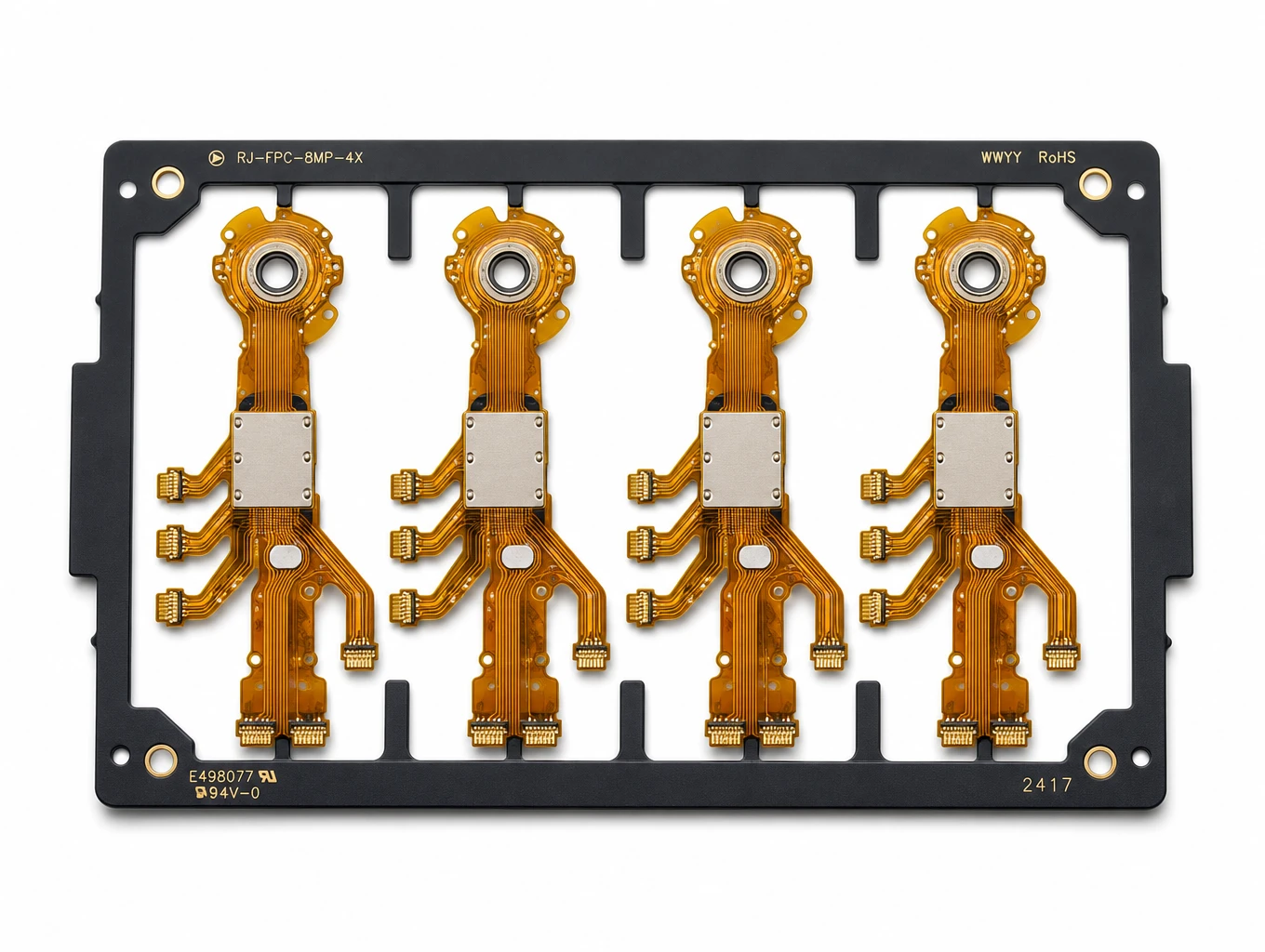
Multi-Branch Humanoid Robotic Joint FPC
Model: TLX-ROB-JNT01
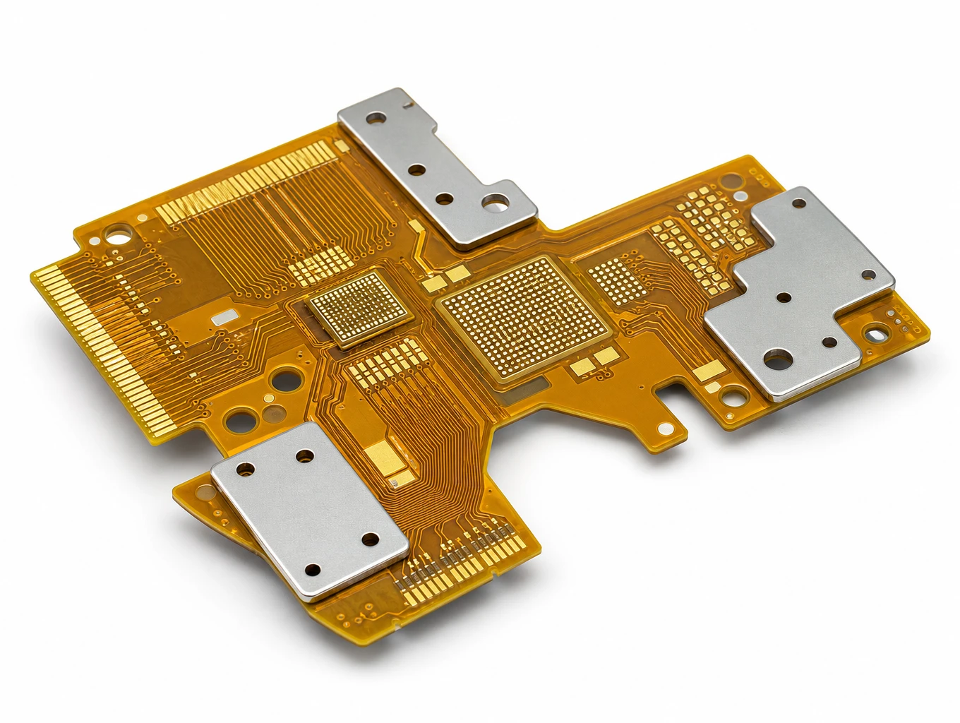
400G/800G High-Speed Optical Transceiver Multi-Layer Flex PCB
Model: TLX-COMM-OPT03
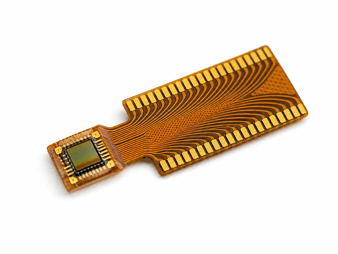
Medical Endoscope Micro-Display FPC
Model: TLX-DFPC-MED06
Related Solutions

AI & Robotics & Special Industrial FPC
Flexible circuits for robotic joints, vision sensors, actuators and industrial interfaces. Match the circuit route to the motion, electrical connections and enclosure of your machine.
Explore Solutions
Smart Automotive Electronics FPC
Automotive FPC products for battery monitoring, ADAS cameras, radar, cockpit displays, steering controls and LED lighting. Select a starting configuration by module function and installation needs.
Explore Solutions
Display FPC
Display FPC products for OLED, AMOLED, micro-LED and TFT-LCD modules in handheld, wearable, automotive and industrial devices. Review the display interface, connector and installed flex shape together.
Explore Solutions AI & Robotics & Special Industrial FPC
Flexible circuits for robotic joints, vision sensors, actuators and industrial interfaces. Match the circuit route to the motion, electrical connections and enclosure of your machine.
Explore Solutions Smart Automotive Electronics FPC
Automotive FPC products for battery monitoring, ADAS cameras, radar, cockpit displays, steering controls and LED lighting. Select a starting configuration by module function and installation needs.
Explore Solutions Display FPC
Display FPC products for OLED, AMOLED, micro-LED and TFT-LCD modules in handheld, wearable, automotive and industrial devices. Review the display interface, connector and installed flex shape together.
Explore SolutionsFrequently Asked Questions
Conclusion: define the circuit by its installed job
A flexible PCB is a patterned electrical circuit built on a bendable dielectric, but that definition does not fully specify a manufacturable part. The finished design depends on layer count, materials, connector interfaces, supported areas and the exact way the circuit bends in the product.
For OEM procurement, the strongest starting point is a shared application description followed by one controlled RFQ package. Compare FPC, FFC, rigid PCB and rigid-flex at system level, then validate the selected structure in its real installed geometry.
To review an application, send the current mechanical drawing, circuit data, quantities, bend condition, assembly scope and test expectations through the Teleconix project inquiry form. The team can return the technical questions that should be resolved before prototype and quotation.