
FPC vs FFC: start with the connection you need
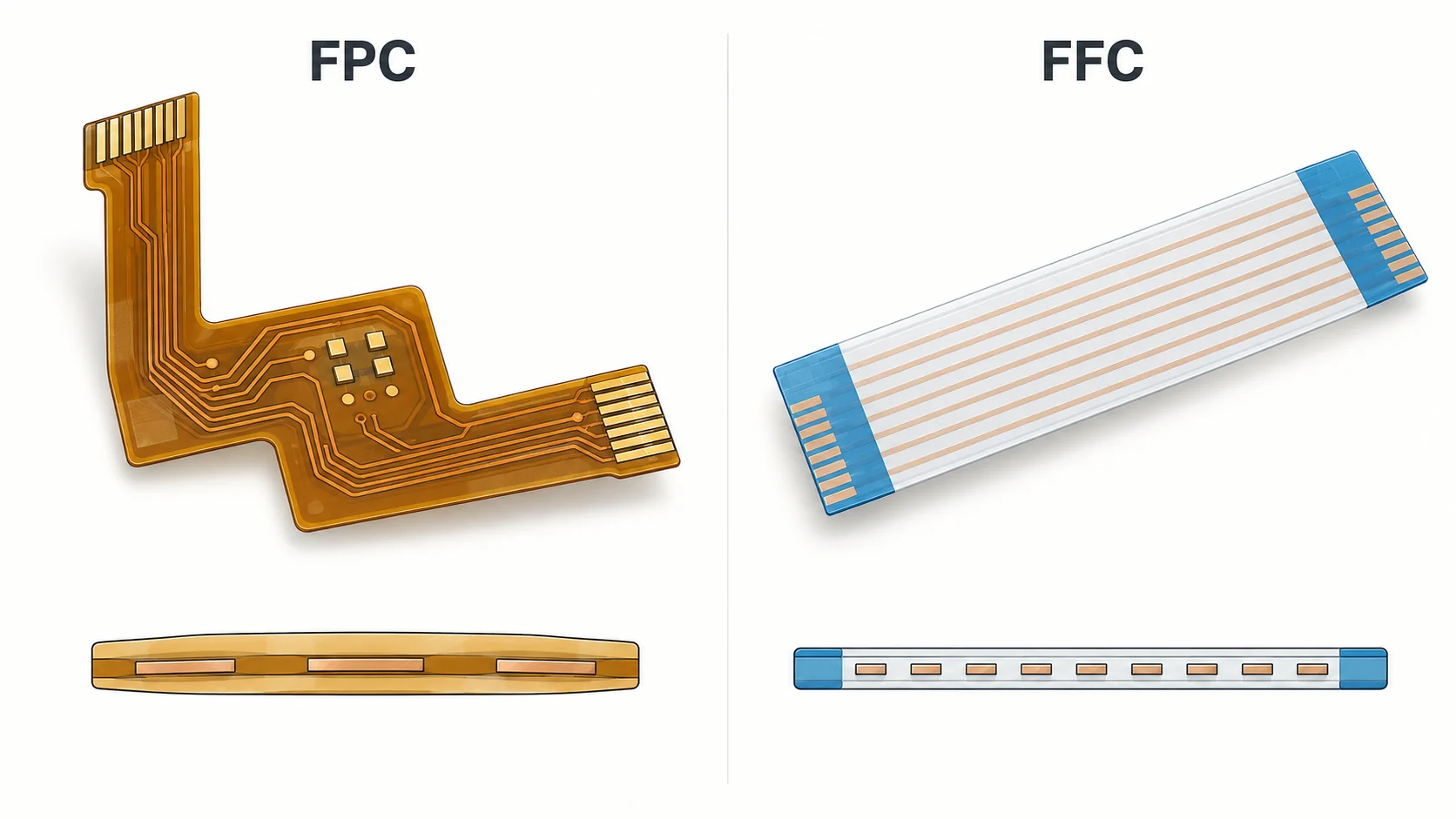
FPC vs FFC is a choice between interconnect constructions, not simply two names for the same orange or white cable. A flexible printed circuit uses patterned conductors on a flexible substrate. A conventional flat flexible cable typically places parallel flat conductors inside an insulating laminate. Both can connect compact assemblies, but their routing options and purchasing documents can differ.
Start with the electrical connections, installed route and assembly method. A standard jumper may suit two aligned connectors. A custom circuit may help when the route branches, changes width or integrates component pads. Neither option is automatically better for every application.
This guide helps OEM engineers and buyers compare the complete connection. It covers connector compatibility, movement, signal requirements, validation and quotation scope. For the wider terminology, see the flexible PCB basics guide. Keep the selected construction and mating drawings together so that an informal cable name does not become the only specification on a purchase order.
Understand the construction behind each name
In this article, FPC means flexible printed circuit and FFC means flat flexible cable. Supplier catalogues sometimes group the terms together or use cable as a general description. Read the actual drawing and construction before deciding what a quoted item contains.
An FPC can route traces around an outline, connect different pad patterns and support selected components or connectors. Its design package normally describes the conductor pattern, layer construction, openings, finishes and supported regions. An FFC jumper is commonly specified by its conductor count, pitch, length, contact arrangement and termination details. Custom cable products can add features beyond a basic straight jumper.
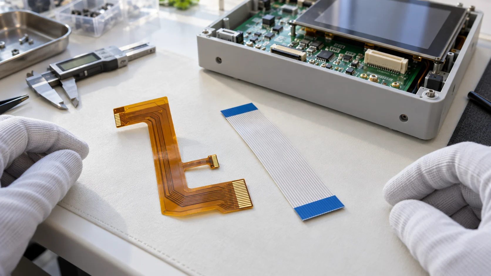
Colour does not identify the full material system or performance. A blue end reinforcement is not proof of a particular mating thickness. An amber flexible circuit is not proof that it is suitable for continuous motion. Ask for the controlled drawing, material description and applicable product specification. Use those documents to compare like-for-like proposals rather than treating a photograph as an engineering definition.
Compare FPC and FFC using the complete assembly
The following comparison is a starting point for a design review. It describes common constructions, not limits that apply to every supplier. Specialised cable assemblies and flexible circuits can overlap in function. Confirm the specific product before rejecting either approach.
| Decision | FPC option | FFC option |
|---|---|---|
| Connection layout | Custom trace routing, shaped outlines and branches can be designed. | A parallel-conductor jumper is often a useful starting point. |
| Integration | Can include defined pads, connectors and assembled components. | Often connects existing interfaces; custom terminations vary. |
| Specification | Circuit artwork, stack-up, fabrication and assembly information. | Cable drawing, conductor arrangement and termination specification. |
| Motion | Requires an application-specific construction and validation. | Requires the cable's motion rating and installed validation. |
| Commercial review | Include tooling, assembly, testing and change control. | Include availability, connector compatibility and installation effort. |
Do not score an option only by its bare-part price. Add the connector pair, supports, assembly time and qualification work. A simpler component can create a more complicated installation, while a custom circuit can introduce its own tooling and revision obligations. Make the trade-off visible before requesting a final quotation.
Check connector compatibility beyond pitch
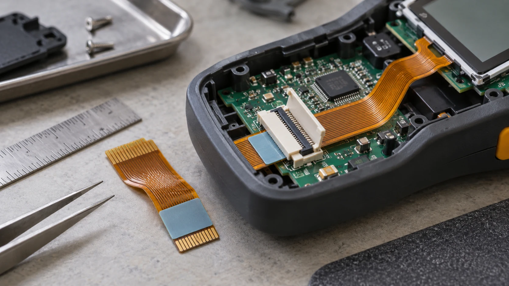
An FFC/FPC connector label does not make every cable interchangeable. Matching pitch and conductor count is only the first check. The mating specification also controls the exposed contacts, insertion geometry, finished thickness, reinforcement and retention features.
- Confirm the exact connector manufacturer, series and part number.
- Check the recommended mating drawing and its revision.
- Match the contact side, insertion direction and cable orientation.
- Review contact length, edge dimensions, tolerances and any locking ears.
- Verify the finished thickness at the contact area and the connector's permitted range.
Do not force an incompatible tail into a connector to make a prototype work. It may damage the contact system or hide a retention problem. Record any approved deviation before the next build.
Hirose's FH12 documentation provides separate drawings and product guidelines for a connector family. Use the item-specific documents for your chosen part. The flexible PCB stiffener guide explains how connector support and mating thickness fit into the wider FPC design.
Make the contact-side and pin mapping explicit
A cable can look correct and still connect the wrong pins. Draw the assembly from a defined viewing direction. Show the exposed conductor side at both ends, pin-one references and the intended connector contact orientation. Include photographs as supporting information, but keep the controlled drawing authoritative.
Supplier labels such as Type A, Type B, same side or opposite side should be checked against that supplier's definition. A naming convention alone is a poor substitute for an unambiguous end-view drawing. Also check whether the system schematic expects a straight-through connection or a different pin mapping.
For an FPC, record the net-to-pad mapping and any component connections. For an FFC, verify conductor continuity between identified ends. Include the mating connectors in the review rather than testing the loose interconnect alone. A sample that passes continuity can still be installed backwards.
Agree how the operator will identify the correct end and orientation during assembly. Useful controls may include permitted markings, asymmetrical outlines, fixtures or a visual work instruction. Validate the chosen method with the actual assembly sequence and service access.
Review the installed route and strain relief
Evaluate the interconnect in the enclosure, not just flat on a desk. Model the complete path between connectors. Include lid closure, nearby fasteners, moving parts, board tolerances and the space needed to insert or release the cable. Avoid a route that depends on an operator making an uncontrolled sharp fold.
A shaped FPC may follow a restricted path or combine several branches. A suitable FFC may provide a straightforward connection between two board locations. Either choice needs adequate support near terminations and protection from sharp edges. A retention feature should not create a new stress concentration in the flexible region.
Use the flexible PCB design checklist to coordinate mechanical and electrical requirements. Review the worst credible installed position, including tolerance stack-up. Check that the enclosure does not pinch the interconnect when it is closed.
Approve a drawing or model showing the intended route, support points and service loop. Give purchasing the same revision used by assembly. This helps prevent a seemingly equivalent replacement from changing the installed stress or blocking access to a connector actuator.
Separate installation bends from repeated motion
Dynamic flex performance belongs to a defined construction and motion profile. Neither the FPC nor FFC label guarantees a particular cycle life. A circuit bent once during installation faces a different problem from a display hinge or carriage that moves throughout its operating life.
Describe the bend direction, radius, moving length, speed, number of cycles and environmental conditions. Include torsion or changing bend locations if the mechanism introduces them. Specify where the part is clamped and how the connector is isolated from movement. A bench test with different supports may not represent the product.
Ask the proposed supplier which construction it recommends for that duty and what evidence supports the recommendation. Agree the sample configuration, electrical monitoring and failure criteria. A mechanical cycle count without a defined acceptance rule cannot settle the comparison.
The static and dynamic bend radius guide covers the design inputs in more detail. Use it to frame the discussion; do not turn a rule from a different material or layer construction into a universal radius requirement.
Specify signal and power requirements as system inputs
For digital links, define the actual interface, route length and relevant electrical targets. Review the full channel, including connectors, transitions and reference paths. A short, ordinary jumper and a specialised shielded assembly do not have the same electrical assumptions.
A custom FPC may provide designed reference conductors, routed pairs or integrated shielding. Specialised FFC assemblies can also address high-speed requirements. Choose using documented construction and validation, not the assumption that every FFC is slow or every FPC has controlled impedance. Molex's cable portfolio illustrates why catalogue products need to be evaluated individually.
For power circuits, review conductor geometry, connector ratings, simultaneous loading and allowable temperature rise. A connector rating is not automatically the current rating of the entire flexible connection. Consider the enclosure temperature, neighbouring circuits and actual duty cycle.
When impedance is required, use the controlled impedance planning guide to define modelling assumptions and test evidence. Keep those requirements separate from visual appearance and nominal pitch.
Define materials, exposure and assembly conditions
Material selection should follow the environment and process. Identify temperature exposure, humidity, cleaning agents, abrasion and any assembly heating. State whether the interconnect is inside a sealed housing or directly exposed. If a product requires a special qualification, provide the actual requirement and evidence expected.
For an FPC, review the substrate, copper, adhesive system, coverlay and reinforcement as a complete construction. For an FFC, request the specified insulation, conductors and termination details. Do not infer a material's suitability from its general name or from a different manufacturer's data sheet.
Assembly also matters. A connection installed after board soldering has different process exposure from a circuit that carries components through reflow. If direct soldering or a hot-bar process is proposed, agree the attachment details and inspection criteria with the parties responsible.
Use the flexible PCB materials guide to organise FPC questions. Confirm any substitutions through change control. An apparently similar material or reinforcement can alter thickness, handling or process behaviour, so an approved sample should be tied to the production construction.
Compare component integration and assembly effort
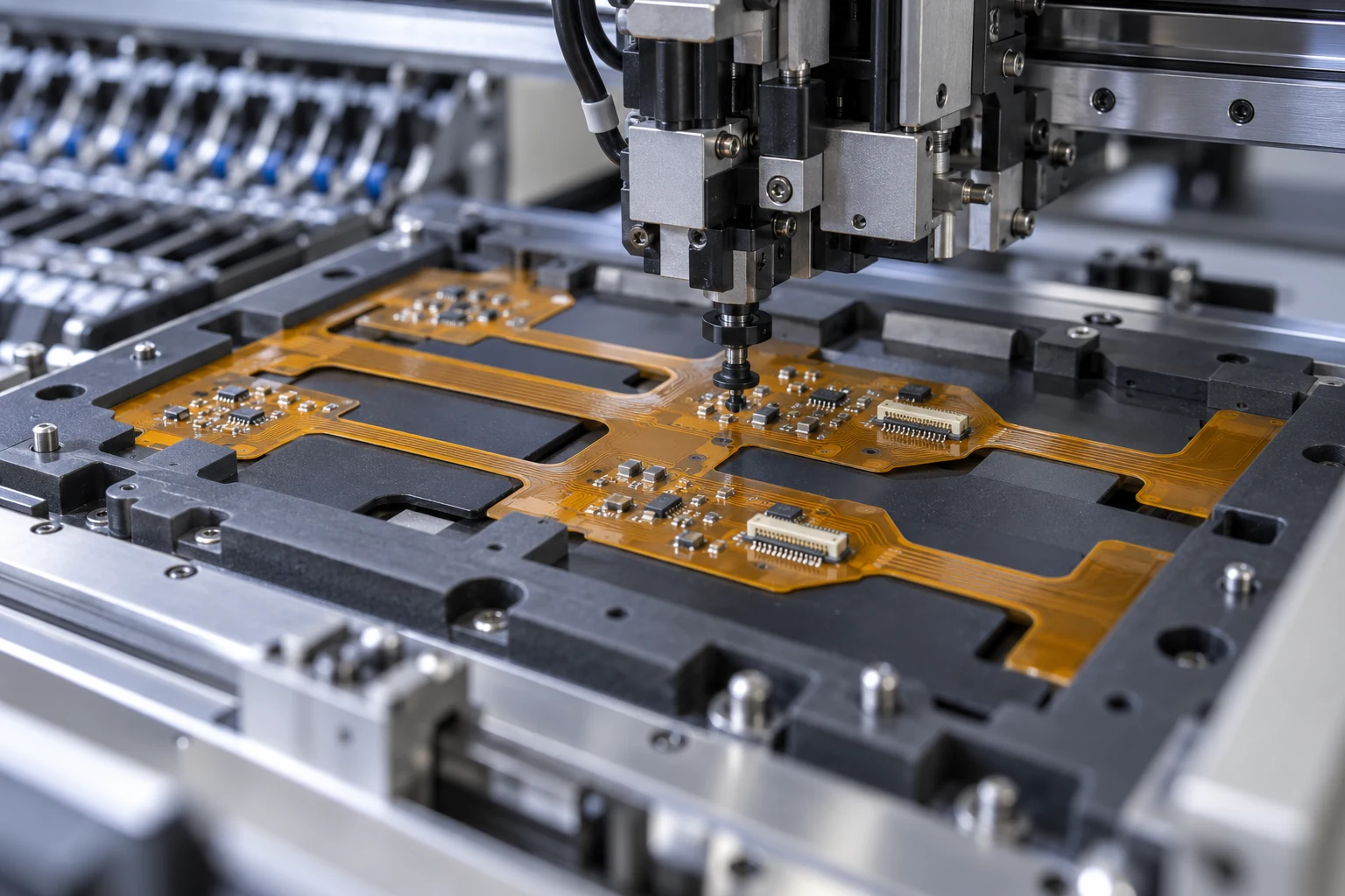
An FPC can be more than a jumper when the circuit includes component pads, connectors or multiple branches. Integration may remove separate interfaces or simplify placement. It also adds responsibilities for sourcing, assembly support, inspection and repair. Review the complete design before assuming integration reduces cost.
A detachable FFC can make sense where existing boards already have compatible connectors and the route is simple. Its benefits may include a clear replacement boundary and access to catalogue variants. Confirm availability, permitted alternatives and handling requirements for the exact cable and connector combination.
Compare the operator's work in both cases. Count insertions, actuator operations, supporting fixtures and visual checks. Review access with the housing partially assembled. Include the consequences of a damaged latch, incorrect orientation or excessive insertion force.
The FPC assembly and quality control guide helps define responsibilities when a custom circuit carries components. Agree whether the quotation covers a bare flexible circuit, an assembled circuit, connector sourcing or a complete tested interconnect. Avoid comparing one supplier's finished assembly with another supplier's bare part.
Validate prototypes in the final installation
Start prototype evaluation with revision-controlled samples and a written acceptance plan. Confirm the dimensions, contact arrangement and connector fit before running functional tests. Check that the operator can assemble the connection using the intended tools and sequence without damage.
- Verify pin mapping, continuity and required isolation.
- Check insertion depth, retention and actuator access.
- Inspect the routed connection with the housing fully closed.
- Run the defined signal or power tests under representative conditions.
- Perform agreed movement and environmental checks where relevant.
Record the fixture, support arrangement and sample identification. Investigate intermittent failures as well as complete opens. A contact disturbed during lid closure may pass a static bench test and fail after installation. Photograph useful observations and link them to the relevant drawing revision.
Use the OEM prototype validation guide to structure the release decision. Prototype approval should identify what was tested and what remains unverified. An acceptable early sample does not automatically qualify a later material, connector or manufacturing change.
Compare total cost and supply risk
Compare quotations against the same functional requirement and volume assumptions. A catalogue FFC may reduce initial engineering effort when it fits the system. A custom FPC may be justified by routing or integration needs. Actual cost depends on the part, quantities, assembly and qualification effort.
Separate recurring costs from tooling and development charges. Include the mating connectors, reinforcement, support hardware, inspection, packaging and assembly labour. Review scrap and rework consequences where they affect the business case. Avoid quoting a universal price difference between FPC and FFC.
Check supply continuity for the exact connector and cable combination. A substitute with the same pitch may differ in contact geometry, thickness or locking features. Ask how changes and discontinuations are communicated and which alternatives require revalidation.
The flexible PCB cost guide explains how design inputs affect a custom quotation. Request the supplier's assumptions and exclusions in writing. Purchasing can then compare complete proposals rather than selecting the lowest line item and discovering additional qualification or assembly work after the order is placed.
Prepare a clear RFQ and a controlled release package
For either approach, provide the function, installed route, quantities and acceptance requirements. Include the exact mating connector drawings and approved end orientation. State the expected prototype stage and which decisions are still open. Give suppliers enough context to identify incompatibilities before quoting.
For a catalogue FFC, add the manufacturer and part number, controlled cable drawing, contact configuration and approved alternatives. For a custom FPC, add circuit artwork or agreed CAD data, net information, outline, layer construction, finish, coverlay openings and stiffener details. Add a BOM, placement data and assembly drawings when components are included.
Record the response to DFM questions and unresolved deviations. Release one agreed revision rather than mixing a new circuit file with an older connector or enclosure drawing. Keep the approved sample and inspection records traceable to that package.
Teleconix's OEM project discussion can start from your application, proposed construction and design files. Confirm the requested FPC scope, materials, assembly and validation requirements for the individual project. This article does not establish a standard FFC supply offering or a fixed performance guarantee.
Use a decision record and the original technical documents
Write a short decision record before the design is frozen. Explain why the selected option fits the route, interfaces, movement and sourcing plan. List the documents that define it, the tests used for approval and any limitations still under review. This record is useful when the design moves from engineering to purchasing or a second supplier is proposed.
For supporting technical context, consult the original manufacturers' documents:
- Molex flexible printed circuit information for examples of routing and component integration.
- Molex FFC/FPC connector information for the range of connection and actuator options.
- Hirose FH12 series documents for an example of part-specific mating drawings and handling guidance.
These are external product references, not statements of Teleconix certification or interchangeability. Use the current specification for the actual part you select. Retain its revision with the OEM design package and reassess the affected checks when that part or construction changes.
Related Products
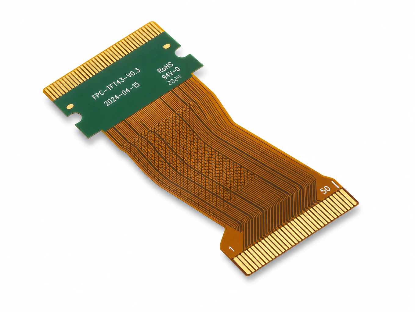
Industrial HMI & TFT-LCD Module FPC
Model: TLX-DFPC-IND05
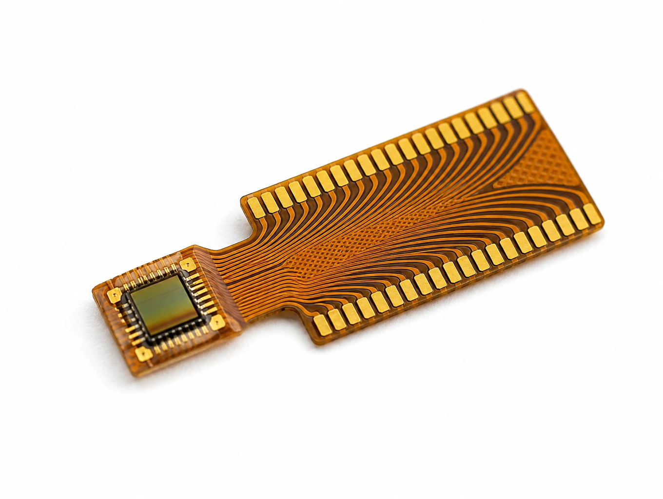
Medical Endoscope Micro-Display FPC
Model: TLX-DFPC-MED06
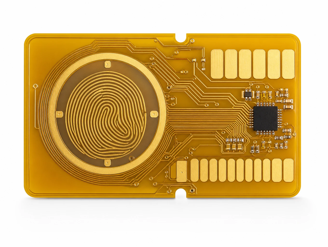
Biometric Smart Payment Card Fingerprint Sensor FPC
Model: TLX-CARD-BIO01
Related Solutions

Medical Device FPC Solutions
Custom flexible circuits for diagnostic equipment, patient monitoring and compact medical electronics. Discuss routing, signal paths, materials and prototype acceptance with Teleconix before releasing your OEM design.
Explore Solutions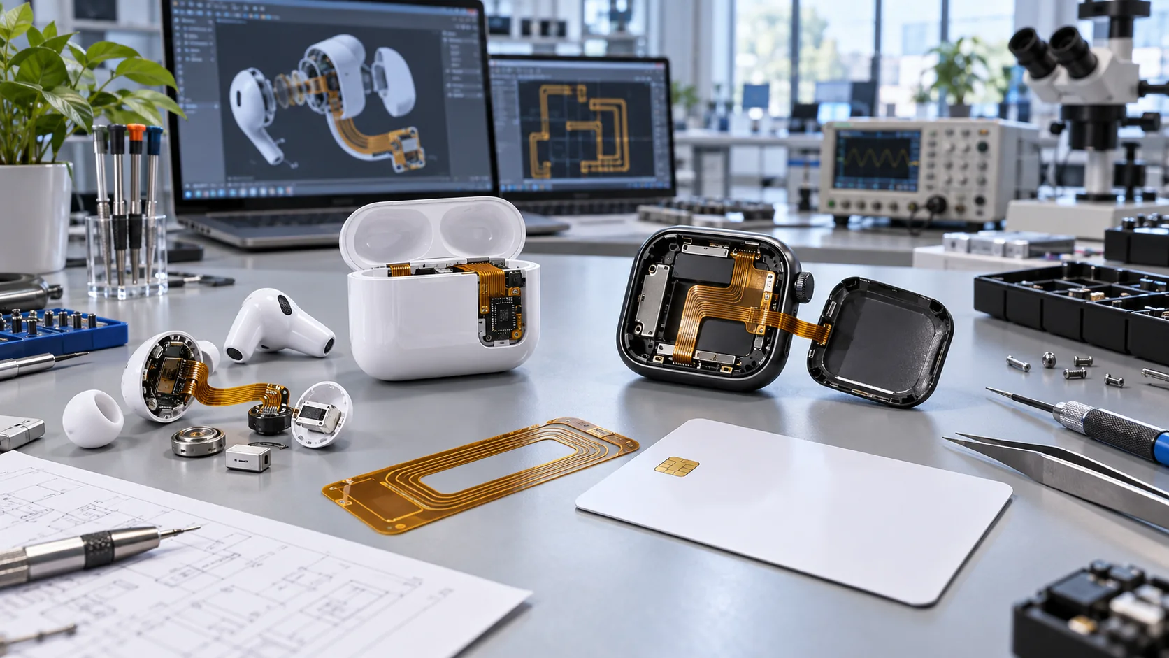
Consumer Electronics & Smart Card FPC Solutions
Custom flexible circuits for smart cards, TWS earbuds and compact wearables. Align routing, stack-up, component interfaces and prototype acceptance with Teleconix before releasing your OEM design.
Explore Solutions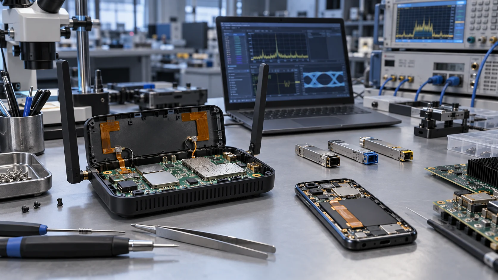
RF & Communication FPC Solutions
Custom RF flexible PCB and telecom interconnects for antenna modules, wireless terminals and high-speed communication assemblies. Coordinate materials, signal paths, shielding and connector support with Teleconix before prototype release.
Explore Solutions Medical Device FPC Solutions
Custom flexible circuits for diagnostic equipment, patient monitoring and compact medical electronics. Discuss routing, signal paths, materials and prototype acceptance with Teleconix before releasing your OEM design.
Explore Solutions Consumer Electronics & Smart Card FPC Solutions
Custom flexible circuits for smart cards, TWS earbuds and compact wearables. Align routing, stack-up, component interfaces and prototype acceptance with Teleconix before releasing your OEM design.
Explore Solutions RF & Communication FPC Solutions
Custom RF flexible PCB and telecom interconnects for antenna modules, wireless terminals and high-speed communication assemblies. Coordinate materials, signal paths, shielding and connector support with Teleconix before prototype release.
Explore SolutionsFrequently Asked Questions
Conclusion: choose a defined and verifiable interconnect
The useful FPC vs FFC decision is the one that produces a defined, compatible and verifiable interconnect. Choose from the actual route and interfaces. Confirm the mating geometry, document the movement and evaluate total assembly cost. Keep the approved construction and acceptance records tied to one revision.
If your design needs a custom flexible circuit, discuss your FPC project with Teleconix. Share the connector drawings, enclosure route and electrical requirements so the proposed construction and service scope can be reviewed before the purchase order is released.