

Rigid flex PCB planning starts with the product architecture
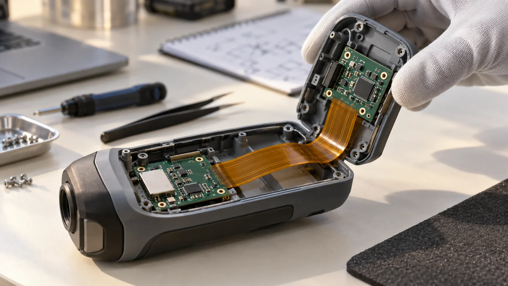
A rigid flex PCB combines rigid circuit regions and flexible interconnect regions within one integrated construction. For an OEM, the practical question is whether that architecture improves the complete product: its installed shape, assembly process, electrical connections and service requirements. A compact enclosure alone is not enough to justify the choice.
Start by listing the problems the interconnect must solve. Perhaps two populated boards occupy different planes, a connector consumes valuable space, or a cable assembly adds handling steps. Describe those constraints before selecting a layer count. This makes the design review a comparison between complete architectures rather than a preference for a particular board technology.
This guide connects design decisions with a sourcing checklist. If your team is still choosing between flexible circuit structures, begin with the flexible PCB basics guide. The examples below are planning concepts; the proposed construction, manufacturing scope and qualification evidence must be confirmed for your actual project.
Distinguish integrated rigid-flex from flex with stiffeners
A stiffener supports a selected area of a flexible circuit, such as a connector interface or an assembly location. Its presence does not automatically make that circuit an integrated rigid-flex board. Ask what the support layer does, how it is attached and which layers carry the electrical connection through each region.
Integrated rigid-flex brings rigid and flexible regions into a coordinated circuit construction. A separate rigid board joined to a flex through a connector is another architecture. These options can serve similar packaging goals, but their fabrication, joining, inspection and replacement responsibilities differ. Name the intended architecture explicitly in the request for quotation.
Würth Elektronik describes multiple rigid-flex constructions and distinguishes them from other flexible circuit solutions. Use that distinction to ask precise questions rather than treating every supported flex as interchangeable. A useful drawing identifies electrical layers, mechanical support and the boundaries of the rigid and flexible regions.
Compare three architectures before committing to rigid-flex
Evaluate an integrated rigid-flex board, separate rigid boards joined by a flexible interconnect, and a flex circuit with localized stiffeners. Compare them using the same enclosure, interface requirements, assembly volume and acceptance plan. A choice that reduces connectors may still add fabrication or assembly complexity elsewhere.
For example, consider an instrument with a sensor board beside a main controller. An integrated circuit may simplify the connection between those planes. A removable interconnect may instead help replace the sensor module during service. The product team should decide which benefit matters and document the assumptions behind that decision.
Create a short comparison covering installed space, connector and joining operations, assembly access, testing, replacement strategy and supply risk. Avoid declaring one approach universally more reliable or less expensive. Reliability depends on the released design and validation; cost depends on the complete purchasing and assembly scope.
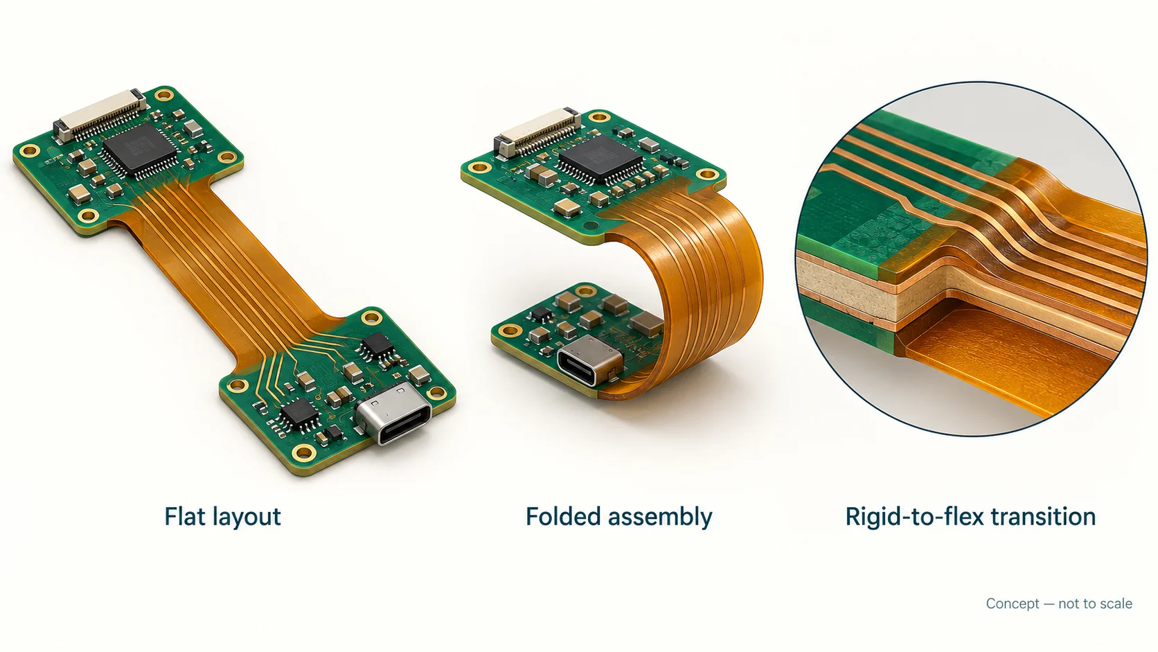
Release both the flat layout and the folded installation view
The supplier needs an unambiguous flat outline for fabrication. The product team also needs an installed view showing how the flexible regions connect the supported rigid islands inside the enclosure. These two views should use the same revision, reference features and coordinate convention so that a layout change does not leave the mechanical drawing behind.
Mark bend locations, intended directions, installed clearances and attachment points. Show where the board can be handled and where it must remain free of clamping or rubbing. Include the connector insertion direction and access needed for assembly tools. A fold that works in a model may be impractical when the surrounding components are installed.
Altium’s rigid-flex design documentation explains regional layer stacks and three-dimensional bending checks. Such tools help communicate the intended geometry, but a model is still a design representation. Review the assembly sequence and representative prototypes before approving the installed configuration for production.
Define a regional stack-up rather than one overall thickness
Specify the construction for each rigid region and each flexible region. Record which electrical layers continue across their boundary and which terminate within a rigid island. Include relevant dielectric, copper, protective and bonding layers in the proposed stack-up. An overall finished thickness cannot describe every cross-section in the same circuit.
Ask the manufacturer to return a proposed stack-up with region names that match the drawing. Engineering should review it before freezing the layout. If a supplier proposes an alternative material system or a different transition construction, record that as a technical alternative with a clear approval requirement.
Use the flexible PCB materials guide to organize material questions. Confirm the particular material grades and construction rather than relying on a generic “polyimide” label. The approved stack-up should become part of the controlled order package and the reference for later changes.
Treat rigid-to-flex transitions as a shared design boundary
The rigid-to-flex transition links two mechanically different regions. Identify it clearly in the design data, then review nearby components, holes, copper features and enclosure supports with the fabricator. A transition detail copied from another project may depend on a different stack-up, process or loading condition.
Ask for the supplier’s recommended clearances and explain what causes loading at the boundary. Handling, folding, connector insertion and enclosure contact can create different stresses. The design review should identify which forces are carried by the rigid island and which may reach the flexible region.
Keep fabrication constraints and assembly restraints in the same discussion. For example, a mounting feature that makes the rigid board convenient to install may force the flex to bend immediately at the transition. Document the accepted geometry and inspection features so production teams can recognize a correctly installed circuit.
Separate a fold-to-install application from repeated motion
A flexible region may be folded during assembly and then remain stationary. Another design may move repeatedly during normal operation. State these conditions explicitly, including handling during maintenance. A construction selected for installation flexibility should not automatically be treated as suitable for continuous movement.
Würth’s rigid-flex guidance identifies standardized constructions intended for flex-to-install applications. That is a useful reminder to qualify the actual use condition. If repeated motion is required, review the proposed materials, copper structure, bend geometry and test plan specifically for that requirement.
Provide the available bend envelope and required motion to the supplier rather than adopting a universal radius multiplier. The static and dynamic flex bend radius guide explains the inputs to that conversation. Agree representative mechanical checks before the enclosure and circuit are both released.
Review copper routing, protective layers and local support
Trace routing must support the electrical requirement while fitting the mechanical construction. Identify sensitive paths, high-current connections and features near a bend or transition. Discuss their placement and shape with the responsible designers. Avoid adding copper features simply because there is unused space in the flat layout.
Coverlay and other protective layers also form part of the construction. DuPont’s Pyralux LF information describes polyimide and adhesive coverlay systems used to protect and insulate flexible circuitry. For your design, specify the actual system and openings, then review how it interacts with assembly and the relevant cross-section.
Show stiffeners, support surfaces and attachment details where they affect connector seating or component assembly. Define who supplies and installs each support item. A drawing should distinguish a fabrication feature from an enclosure part; otherwise two suppliers may price different responsibilities while appearing to quote the same board.
Model electrical behaviour through every relevant region
A signal path can cross rigid material, a flexible region and a transition before reaching a connector or component. Identify which portions require controlled impedance or additional channel evaluation. The designer should review the relevant cross-sections and reference paths rather than assuming one trace rule applies throughout the complete assembly.
Document target requirements, applicable interfaces, return paths and the responsibility for analysis. If a fabrication coupon is proposed, ask which structure it represents. A coupon can support a defined acceptance check without representing every launch, connector or installed condition in the complete product.
Refer to the controlled impedance flex PCB planning guide when preparing those requirements. Keep electrical continuity, impedance acceptance and assembled-system verification separate in the RFQ. Each should have an identified test boundary, owner and required evidence.
Plan assembly access and support before releasing the BOM
Populated rigid regions may need carriers or fixtures during printing, placement, reflow and inspection. Agree how the complete circuit is supported and how flexible connections are protected during handling. Clarify whether assembly takes place before folding and which operations must remain accessible after the installed shape is formed.
Supply the component bill of materials, placement data, assembly drawings and any special orientation requirements. Mark which items are customer supplied and which are included in the quotation. If the final assembly includes connectors, shielding parts or enclosure hardware, identify their installation and inspection responsibilities.
The FPC assembly and quality control guide gives a broader assembly checklist. For rigid-flex, add the support method, island handling and fold sequence. A successful fabrication sample does not by itself establish that the populated assembly can be built and inspected consistently.
Define acceptance evidence that matches the delivered scope
Separate bare-board acceptance from assembly acceptance and complete-product qualification. For fabrication, identify the drawing revision, electrical connectivity checks, dimensional requirements and agreed records. For assembly, state the required inspection and functional checks. For the product, specify the installation conditions and qualification responsibilities.
IPC’s public IPC-2223 scope addresses flexible and rigid-flex design alongside related board design documents. Reference an agreed applicable document and revision where your contract needs one. Do not turn a standard’s name into a broad supplier certification claim or assume that a public contents page provides every acceptance criterion.
Agree which evidence accompanies a shipment and which remains available on request. Tie records to the lot and revision. If a customer requires particular qualification or certification evidence, review the actual documents and scope before promising compliance. Procurement should receive the same technical baseline that engineering approved.
Build an RFQ package with explicit assumptions and exceptions
A useful rigid flex PCB RFQ includes controlled fabrication data, regional stack-ups, flat and installed drawings, quantity and milestones. Add assembly data where assembly is included. State the required reports, delivery scope, packaging expectations and the person authorized to approve technical substitutions.
Ask each supplier to return a marked assumptions-and-exceptions list. Questions about bend geometry, material availability, tolerances, tooling or inspection should be resolved before order release. Where an item remains open, identify the decision owner and the date or prototype stage at which it must be closed.
Keep the quotation baseline readable. A buyer should be able to locate the chosen construction, test scope and revision without searching through email attachments. If the design changes during quotation, issue a new controlled package and ask suppliers to acknowledge which revision their pricing and lead-time assumptions cover.
For a design involving several teams, include a simple responsibility matrix. Identify who releases the enclosure geometry, who approves the regional stack-up, who owns electrical analysis and who accepts the first article. Record a separate owner for assembly and product qualification. This prevents an unresolved engineering decision from being passed silently to purchasing or the fabricator when the order is placed.
Compare total delivered cost and the replacement strategy
Compare board fabrication, tooling, assembly support, component joining, inspection and qualification work together. Record one-time and recurring items separately. An integrated circuit may remove some connection operations while adding other costs; the relevant outcome is the complete delivered assembly under an equivalent specification.
Consider what happens when one region is damaged or a component fails during service. If the architecture makes several functional islands inseparable, the replacement unit may be larger than in a modular design. Engineering, procurement and service teams should evaluate that consequence before selecting the construction.
Use the flexible PCB cost drivers guide to organize quotation comparisons. Ask for the basis of any proposed simplification rather than accepting a percentage-saving claim without a matching baseline. A lower unit price is meaningful only when the quoted design and acceptance scope are comparable.
Approve representative prototypes and control later changes
The prototype plan should resolve the risks identified in the architecture review. Check flat geometry, installed fit, support, assembly access and the required electrical behaviour. Where motion or service handling matters, use an agreed representative setup. Record the tested configuration and the limits of the evidence obtained.
Follow the OEM prototype and validation guide for first-article preparation. For rigid-flex, add region identification and the folding sequence to the acceptance checklist. Preserve the as-built stack-up and any approved departures so a repeat order can refer to an identifiable accepted construction.
Define which later changes require review: material substitutions, stack-up changes, artwork revisions, connectors, support features and assembly processes may all affect the accepted configuration. Establish notification and approval responsibility before repeat production. This gives the sourcing team a controlled baseline for future orders rather than a drawing with undocumented assumptions.
Technical references: Würth Elektronik rigid-flex constructions; Altium rigid-flex design documentation; DuPont Pyralux LF coverlay data; IPC public IPC-2223 scope. These sources explain construction and design concepts; they do not establish Teleconix certification or approve a particular production design.
Related interconnect products for architecture review
Review the rigid-flex example alongside compact flexible interconnect applications when comparing architectures. These product pages describe different constructions; confirm the proposed stack-up, available manufacturing scope and project-specific qualification evidence during technical review.
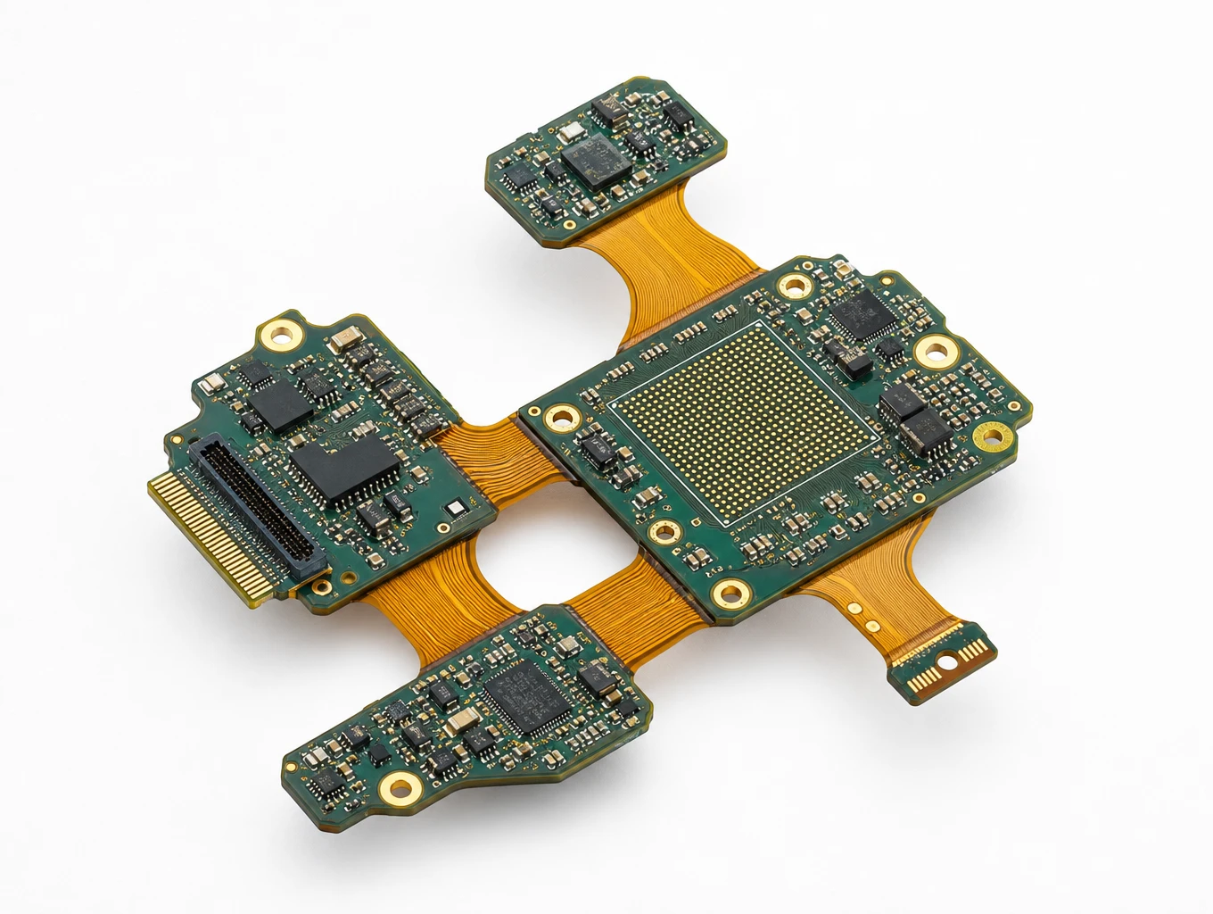
IPC-6013 Class 3 Flight Avionics Autopilot Rigid-Flex PCB
Model: TLX-AERO-AVN03
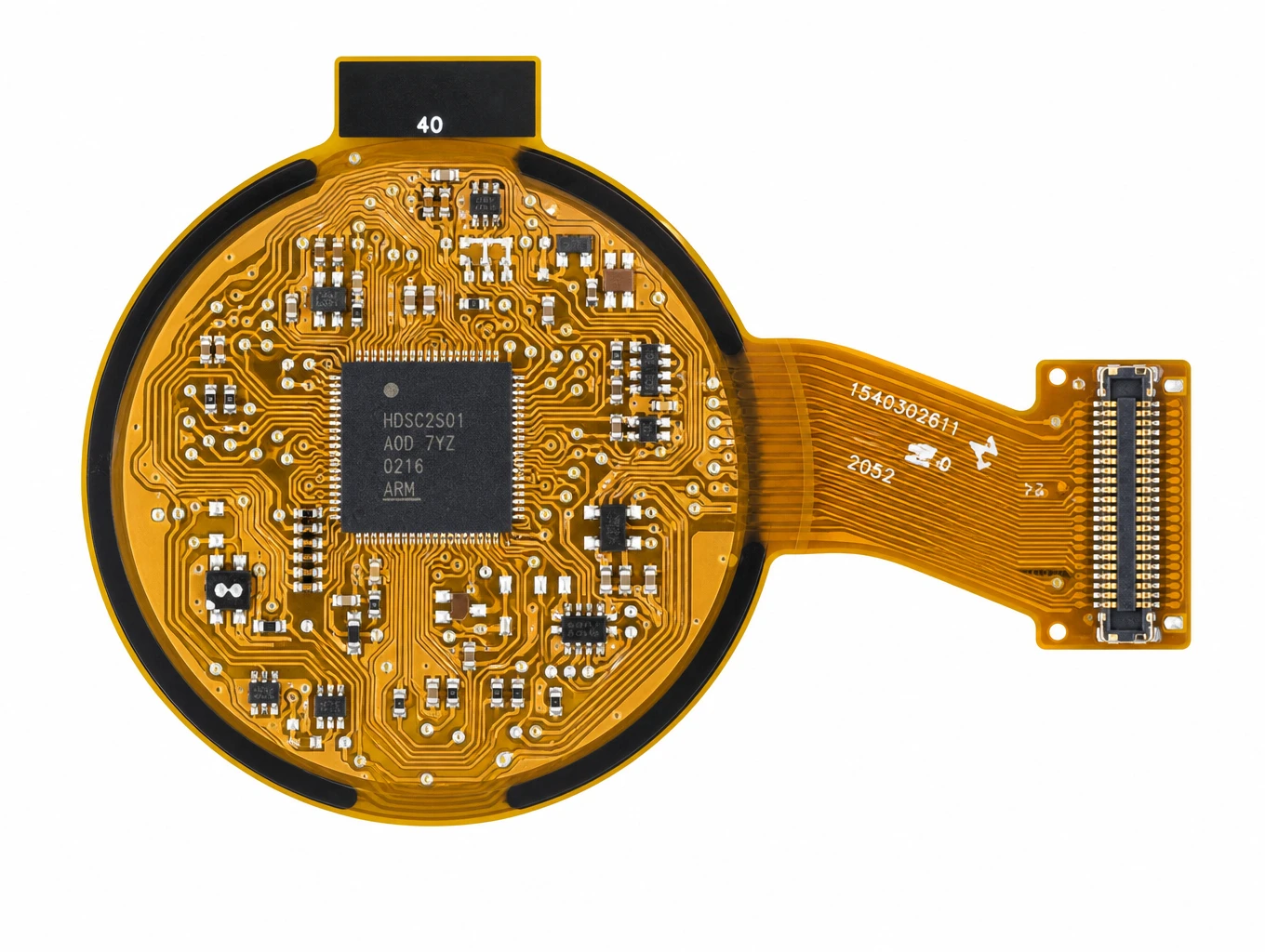
Wearable Smartwatch & Round AMOLED FPC
Model: TLX-DFPC-WEAR04

Smart Wearable Health Ring & Biosensor Multi-Flex FPC
Model: TLX-CONS-RING06
Related solutions for compact and three-dimensional electronics

High-End Industrial UAV & Commercial Aerospace FPC
Teleconix manufactures aerospace-grade flexible circuits built to IPC-6013 Class 3 standards for industrial drones, flight avionics, multi-axis gimbals, and satellite systems — delivering superior SWaP weight reduction, extreme thermal endurance, and fail-safe signal integrity.
Explore Solutions
AI & Robotics & Special Industrial FPC
Overcome severe mechanical stress and extreme spatial constraints in your automated hardware. We design and manufacture custom flexible circuits engineered to endure over 2 million continuous bending cycles in multi-axis robotic joints, bionic grippers, and autonomous AGV/AMR platforms.
Explore Solutions
Consumer Electronics & Smart Card FPC Solutions
Custom flexible circuits for smart cards, TWS earbuds and compact wearables. Align routing, stack-up, component interfaces and prototype acceptance with Teleconix before releasing your OEM design.
Explore Solutions High-End Industrial UAV & Commercial Aerospace FPC
Teleconix manufactures aerospace-grade flexible circuits built to IPC-6013 Class 3 standards for industrial drones, flight avionics, multi-axis gimbals, and satellite systems — delivering superior SWaP weight reduction, extreme thermal endurance, and fail-safe signal integrity.
Explore Solutions AI & Robotics & Special Industrial FPC
Overcome severe mechanical stress and extreme spatial constraints in your automated hardware. We design and manufacture custom flexible circuits engineered to endure over 2 million continuous bending cycles in multi-axis robotic joints, bionic grippers, and autonomous AGV/AMR platforms.
Explore Solutions Consumer Electronics & Smart Card FPC Solutions
Custom flexible circuits for smart cards, TWS earbuds and compact wearables. Align routing, stack-up, component interfaces and prototype acceptance with Teleconix before releasing your OEM design.
Explore SolutionsFrequently asked questions about rigid flex PCB sourcing
Discuss your rigid flex PCB design and sourcing package
A practical rigid flex PCB sourcing decision connects the product architecture with regional stack-ups, transition details, an assembly plan and defined acceptance evidence. Compare alternative constructions, resolve supplier assumptions and approve representative prototypes before releasing repeat production.
Review Teleconix’s OEM and ODM collaboration page and send your flat outline, installed drawing, proposed stack-up, quantity and required records through the contact page. Discuss the proposed rigid-flex construction, available manufacturing scope and qualification requirements during technical review before treating them as confirmed project commitments.