
AI glasses FPC requirements start with the product architecture
An AI glasses FPC connects defined electronic functions inside the frame while fitting the temples, front housing and any moving hinge route. Begin with the product architecture. Identify the camera, microphones, speakers, controls, power connections and processing boards actually included in the design. Add a display connection only when that version of the glasses contains a display.
Qualcomm's AI glasses platform overview describes camera, audio, connectivity and display-related capabilities, and distinguishes glasses with and without displays. It illustrates the range of architectures in this category. It does not establish the interface, construction or performance of an individual flexible circuit. The OEM still needs a controlled module and connection map.
For a hardware or purchasing team, the practical question is what the FPC supplier must deliver and what the complete eyewear programme must verify. A passive camera tail, a populated temple assembly and an antenna flex have different boundaries. State whether the requested scope includes components, connectors, reinforcement, bonding, electrical testing or installation into the frame.
Build an interface map before freezing the outline
- Give every module and connector a unique reference and an owner.
- Identify which electronics sit in each temple, the front frame or another assembly.
- Mark fixed connections, installation folds and spans affected by folding the glasses.
- List open architecture decisions separately from approved manufacturing inputs.
The broader consumer electronics FPC integration checklist provides the parent workflow. This guide develops the eyewear-specific handoff between module selection, frame design, assembly and prototype review. Keep those decisions connected so a change to one temple does not silently invalidate a circuit ordered for the earlier frame.
Map the temple, front frame and left-right interfaces
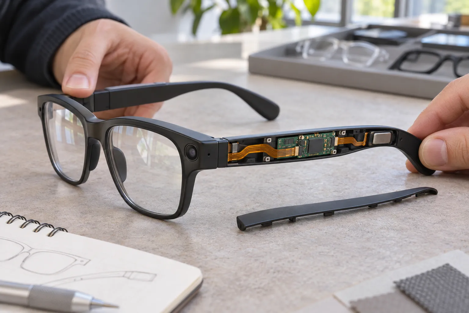
Release installed mechanical views that show where the circuit goes inside the glasses. Include the temple covers, hinge hardware, screws, optical modules, speaker cavities and board supports. Identify the datum used to locate each board and tail. A flat drawing can describe fabrication without showing whether the assembled circuit reaches its connector or clears the closing cover.
Define the left and right assemblies explicitly. A mirrored frame does not automatically permit a mirrored pin map, contact side or component placement. Show the viewing direction on drawings and identify the mating face at both ends. Use a controlled part identifier for each circuit when the two sides differ. Ask mechanical and electrical reviewers to sign off the same orientation record.
Use a short placement matrix
| Location | Decision to define | Evidence to review |
|---|---|---|
| Front frame or camera corner | Module datum, optical clearance and connection access | Installed view with the actual camera or sensor envelope |
| Temple electronics | Board position, speaker cavity and cover closure | Supported circuit route and assembly sequence |
| Hinge crossing, if present | Fixed ends, moving span and full folding travel | Views through movement and a representative fit sample |
| Charging or service interface | Contact location, access and permitted handling | Inspection stage and mating or service instruction |
Check manufacturing and assembly variation as well as nominal geometry. Board location, frame dimensions, cover features and tail length can all affect the installed route. Let the responsible designer specify the acceptance dimensions and the conditions needing boundary samples. Record where excess length is accommodated. An installer should not have to invent a fold or tuck an unsupported ribbon beside a screw to close the housing.
Classify hinge motion and reserve a repeatable flex route
Determine whether the circuit actually crosses a folding interface. Some smart glasses connections remain entirely within a fixed temple or front-frame section. Others change shape each time the temples fold. Classify installation, service and normal-use movement separately. The word wearable does not establish the duty of every flexible region.
Where an FPC crosses the hinge, show both endpoints and the complete movement between the open and folded positions. Include intermediate poses where the ribbon approaches the hinge barrel, screw, cover edge or another part. Look for pinching, rubbing, local buckling and tension at the ends. Identify which span is intended to move and which regions must remain supported.
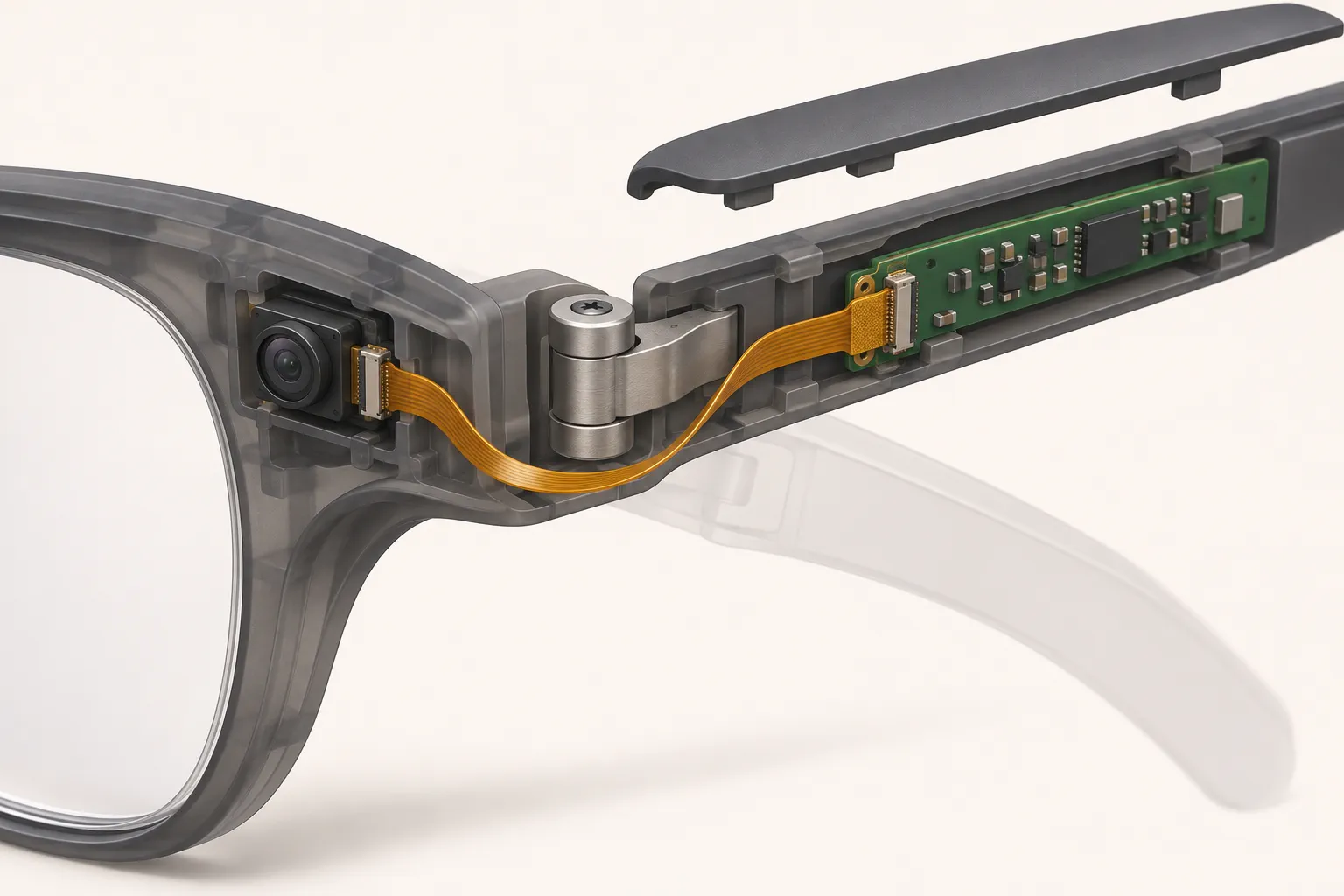
Review the closed assembly as well as the open model
A route may look acceptable with the temple cover removed and change when the cover is installed. Try a representative assembly method and observe how the flex settles. Record the approved support locations, orientation and loading sequence. If movement depends on an uncontrolled crease or contact with a sharp edge, return the route to the mechanical review before treating the sample as ready for further testing.
Use the static and dynamic flex bend guide to describe the bending conditions. Select the construction and working geometry together. Avoid attaching a universal radius or folding-life promise to the words thin, polyimide or rolled annealed copper. Any motion claim needs the actual specimen, supports, movement and acceptance conditions.
Specify camera, audio and optional display connections
Give the electronics reviewer an interface record for each module. Identify the selected device, connector pin map, supply connections, reference paths and applicable module documentation. Separate camera data, audio, controls and power in that record, even when they share a circuit outline. The AI processing function does not replace the electrical requirements of those connections.
MIPI Alliance's CSI-2 camera interface overview identifies CSI-2 as an image-sensor interface and describes different physical-layer implementations. For a camera flex, establish the implementation used by the selected sensor and processor. Have the responsible designer approve the channel requirements. A camera's resolution alone does not define conductor geometry, lane assignment or an acceptable assembled link.
Identify the actual microphone and audio interfaces in the same way. Document their reference connections, required routing constraints and proximity to switching circuits or speaker connections. Record any restrictions supplied by the component designer. Check whether a symptom belongs to the interconnect, audio configuration, acoustic arrangement or another part of the product before assigning it to the FPC.
Treat display and wireless functions as defined branches
If the glasses include a display, provide the display module, interface documents and installed optical assembly. Define who verifies image operation and alignment. Use the display FPC integration guide for that branch of the review. Keep it out of the circuit specification for a version without a display.
Also distinguish a radio antenna from a data interconnect. State whether antenna design, tuning or final device checks are included in the supplier scope. The selected radio and antenna team should approve the route and surrounding materials. Where controlled impedance is required, define the model and acceptance method for the actual channel rather than applying one generic target to every signal in the glasses.
Control connector fit, reinforcement and the full local stack
Specify the full mating connector part number at each endpoint. Review contact orientation, pin numbering, finished tail thickness, insertion depth and latch access with the actual component drawing. Fine pitch alone does not establish compatibility. Show how an operator reaches the connector after nearby modules are fitted and how the tail is supported during insertion.
Hirose's FH35C connector information is a useful example of a catalog defining contact arrangement, actuator style and compatible FPC thickness. Those details belong to that connector family. They demonstrate the need to check the selected part, not a recommendation that every AI glasses design should use that series or inherit its specifications.
Record the complete construction at the tail, moving span, bonded area and populated region. Include conductor, dielectric, coverlay, finish, reinforcement and adhesive where applicable. A total thickness written for the free span may differ from the finished connector tail. Show where layers start and stop so the mechanical reviewer can evaluate the transitions.
Keep support changes visible in the drawing set
Use the connector stiffener planning guide to organise local support and measurement locations. Define the free route beyond the reinforced area. The intended folding action should not depend on the circuit bending at an unspecified stiffener edge or pulling on the contacts. Confirm fit with representative finished tails, mating parts and enclosure features.
Ask the supplier to identify proposed material alternatives and any assumptions behind them. A substitute with similar nominal thickness can still change fit, handling or the moving construction. Agree which changes need renewed review before purchasing accepts them. Keep the approved stack-up, connector drawings and installed route on the same release manifest.
Plan assembly, power routing and exposure at the frame
Write the installation sequence before the frame is frozen. Identify the safe unpowered assembly condition, temporary support, connector mating order and cover closure. Protect camera windows, acoustic openings and exposed contacts during handling. Specify where adhesive is applied and how the circuit is held while that operation is completed. Review the sequence with the people who will build the samples.
Identify which power and charging paths actually use the FPC. Give the electronics team the load states and the contact, voltage-drop and thermal checks needed for that route. State the relationship to the selected battery and protection electronics. A conductor thickness or a flexible substrate name cannot establish the runtime, temperature rise or safety of the complete glasses.
Describe the conditions the installed circuit sees
Map local heat sources and any exposure paths through the frame. The product requirements may include humidity, sweat, cleaning, handling or other conditions. Distinguish a protected internal connection from an exposed charging or service interface. Assign the verification conditions to the product team and record the construction that the test covers.
Assess bonding materials and assembly processes in the same review. A cleaning agent, adhesive change or revised cover seal can affect a connection even if the copper artwork is unchanged. Do not infer a finished-device ingress rating or skin-contact suitability from coverlay alone. Obtain the relevant evidence for the actual materials and finished device when the programme requires it.
For populated delivery, use the FPC assembly planning checklist to define BOM ownership, placement data, support tooling, inspection stages and rework limits. Include access to test points before they become hidden. Make each check part of an identifiable build step so a later failed sample has a useful assembly history.
Verify the AI glasses FPC in representative assembled samples
Give each prototype build a decision to support. An early sample can establish fit and assembly access. A later build may evaluate the folding route, camera or audio operation and relevant exposure conditions. Record which questions the build answers and what remains outside its scope. Approval should follow identified evidence rather than a general statement that the glasses work.
Start with part identity, drawing revision, module orientation, connector seating and support position. Inspect the circuit after the housing is closed. Check the defined operating states with the actual electronics and software configuration recorded. Where a display is fitted, include its relevant checks separately. Preserve sample identifiers, observations and deviations with the results.
Separate fit, function and recurring movement
- Fit: installed outline, cover closure, contact engagement and clearances.
- Function: the agreed camera, audio, control, power and optional display checks.
- Movement: the defined folding sequence with suitable observation and electrical monitoring.
- Environment: checks tied to the selected materials, local exposure and complete assembly.
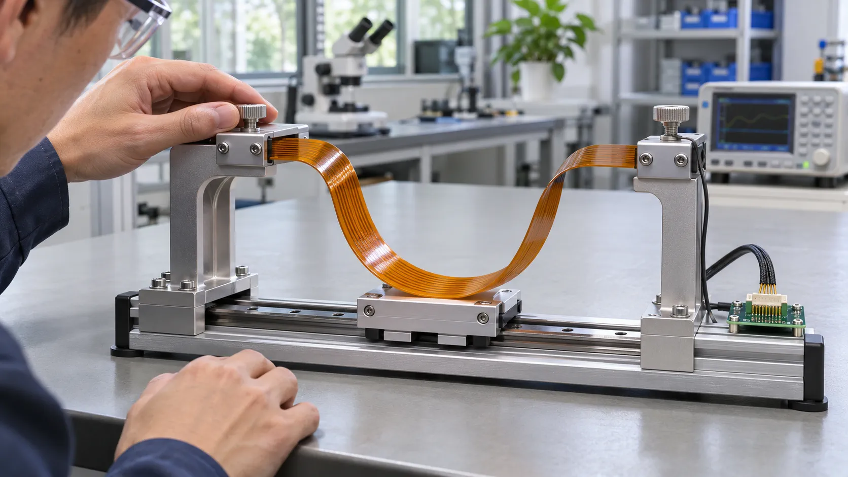
For a recurring hinge route, use the flex PCB fatigue testing checklist to define specimen, fixture, movement, monitoring and endpoints. Choose the sample plan and duration with the responsible reviewers. A result on a different ribbon or support arrangement should retain its original scope.
If a camera or microphone intermittently disconnects, record the pose, operating mode and exact symptom before replacing parts. Preserve the sample and compare relevant conditions methodically. A flat-board electrical pass does not demonstrate every installed function. When the investigation changes the route, support or construction, identify which checks need repeating and retain the earlier revision's evidence separately.
Release an AI glasses FPC RFQ with one controlled file set
Build a quotation package around the approved interfaces and frame revision. Include circuit data, outline and drill information, proposed construction, connector drawings, reinforcement details and installed views. For assembly, add the controlled BOM, placement information and drawings. Identify customer-supplied components and the party responsible for installing the completed circuit into the glasses.
Use the flexible PCB RFQ file checklist to create a release manifest. Add left-right identification, hinge duty, assembly sequence and prototype acceptance requirements. Separate sample and production quantities. Ask each proposal to state fabrication, tooling, components, assembly, inspection and testing scope so purchasing can compare equivalent deliverables.
Example: resolve a camera-audio temple connection
Consider an illustrative camera-and-audio eyewear design without a display. The camera sits near the front corner and processing electronics sit in a temple. Before requesting a circuit, the team confirms whether the connection crosses the folding interface. It releases the two mating interfaces, a route through the frame and the assembly method used to close the temple cover.
The first build checks identity, access, installed fit and the defined camera and audio functions. If the flex moves during folding, the team then evaluates that duty using an approved plan and representative supports. A changed hinge or cover returns the affected decisions to review. This is an engineering planning example, not a Teleconix customer case or a measured endurance result.
Before a reorder, reconcile the accepted sample with the released files and approved changes. Confirm who owns the circuit design, frame integration, antenna work and final product verification. Keep unresolved decisions and their owners visible. A clear delivered boundary helps an OEM source an AI glasses FPC without confusing circuit manufacture with complete eyewear development or certification.
Use a release worksheet to record the required evidence beside each decision. For connector fit, identify the tail drawing and mating-part review. For folding, identify the approved route and sample report. For a camera or audio function, identify the tested hardware and software configuration. Give each item a reviewer and a disposition. Record deviations in that same worksheet, including whether they apply only to the prototype order or also to a later build. This gives purchasing a clear basis for releasing the agreed configuration.
Related Audio and Optional Display FPC Products
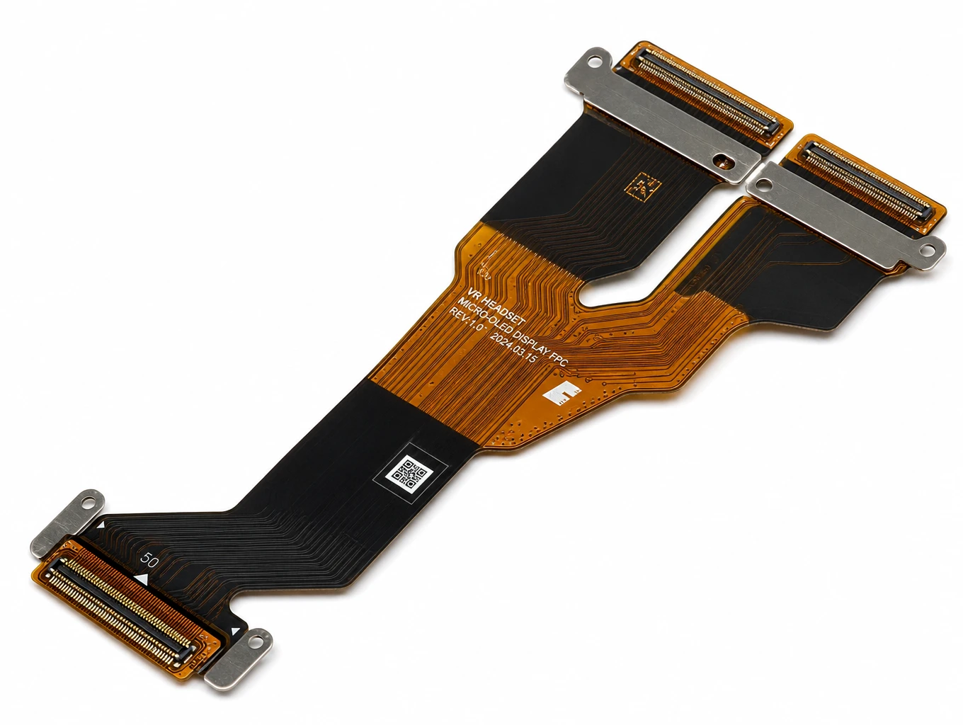
High-Refresh Micro-LED & VR/AR Display FPC
Model: TLX-DFPC-MLED02
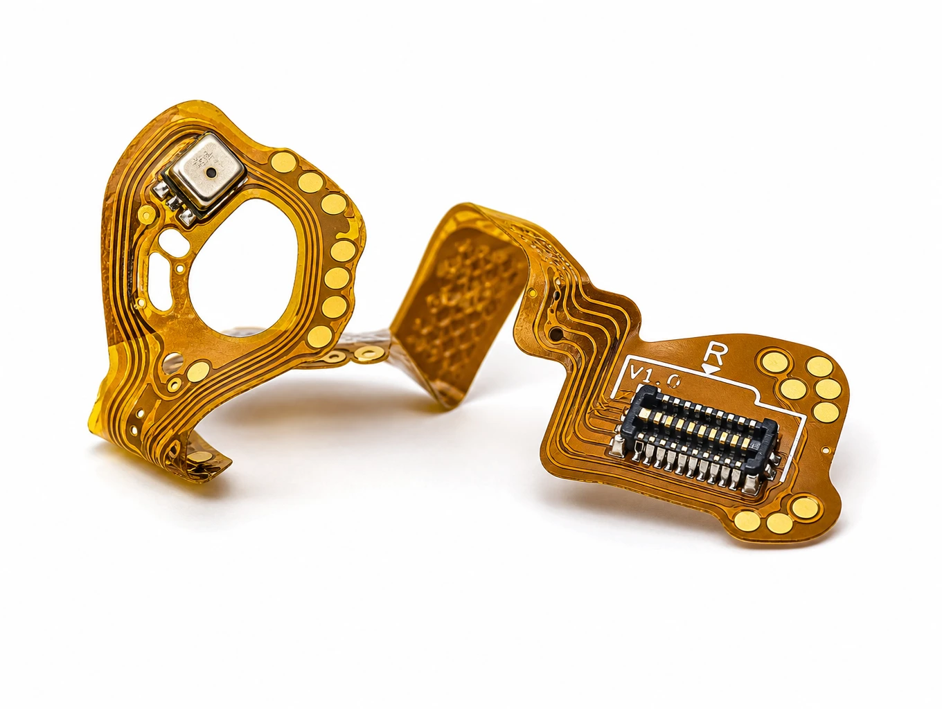
True Wireless Stereo (TWS) Earbud & Charging Case Micro FPC
Model: TLX-CONS-TWS05
Related FPC Application Solutions
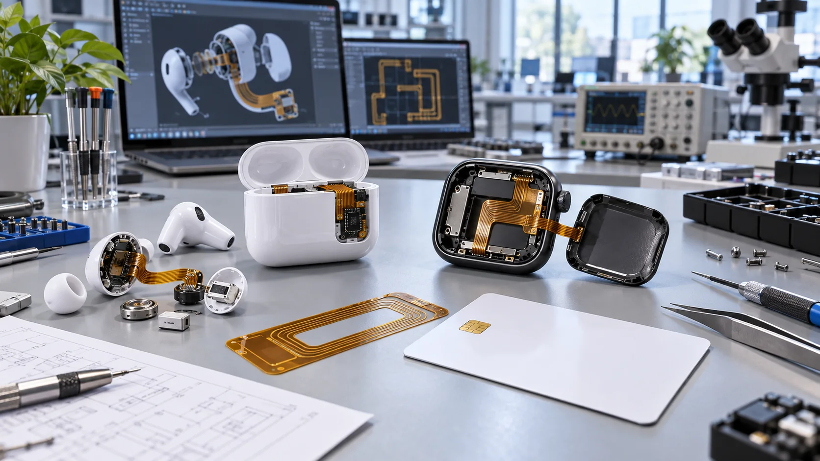
Consumer Electronics & Smart Card FPC Solutions
Custom flexible circuits for smart cards, TWS earbuds and compact wearables. Align routing, stack-up, component interfaces and prototype acceptance with Teleconix before releasing your OEM design.
Explore Solutions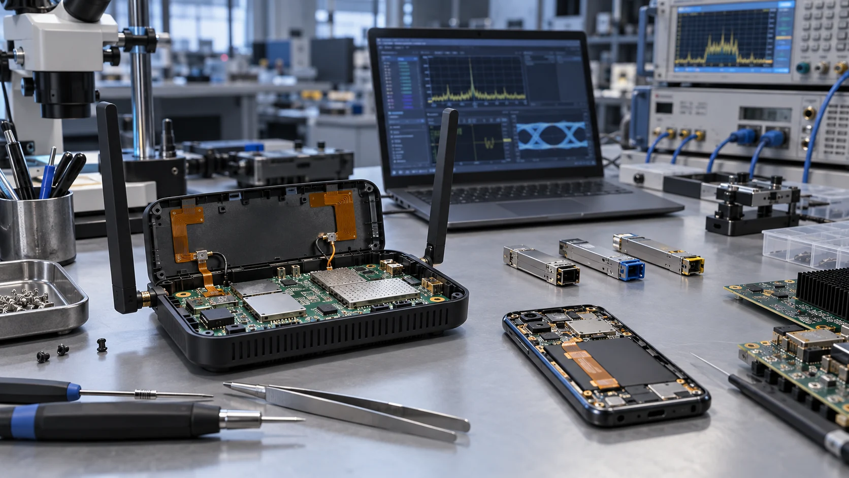
RF & Communication FPC Solutions
Custom RF flexible PCB and telecom interconnects for antenna modules, wireless terminals and high-speed communication assemblies. Coordinate materials, signal paths, shielding and connector support with Teleconix before prototype release.
Explore Solutions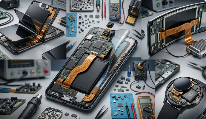
Display FPC
Display FPC products for OLED, AMOLED, micro-LED and TFT-LCD modules in handheld, wearable, automotive and industrial devices. Review the display interface, connector and installed flex shape together.
Explore Solutions Consumer Electronics & Smart Card FPC Solutions
Custom flexible circuits for smart cards, TWS earbuds and compact wearables. Align routing, stack-up, component interfaces and prototype acceptance with Teleconix before releasing your OEM design.
Explore Solutions RF & Communication FPC Solutions
Custom RF flexible PCB and telecom interconnects for antenna modules, wireless terminals and high-speed communication assemblies. Coordinate materials, signal paths, shielding and connector support with Teleconix before prototype release.
Explore Solutions Display FPC
Display FPC products for OLED, AMOLED, micro-LED and TFT-LCD modules in handheld, wearable, automotive and industrial devices. Review the display interface, connector and installed flex shape together.
Explore SolutionsFrequently Asked Questions
Conclusion: connect eyewear integration to release evidence
An AI glasses FPC specification should connect the selected modules to the actual temple and frame route. Define left-right interfaces, hinge duty, connector support, assembly steps and prototype checks together. Keep optional displays and antenna responsibilities explicit, and retain evidence for the exact construction and frame revision that the team approves.
To prepare an OEM review, discuss your AI glasses FPC requirements with Teleconix. Share module and connector documents, installed mechanical views, available circuit files, expected movement and the requested verification scope. Confirm the proposed fabrication and assembly services for your individual project before authorising a build.