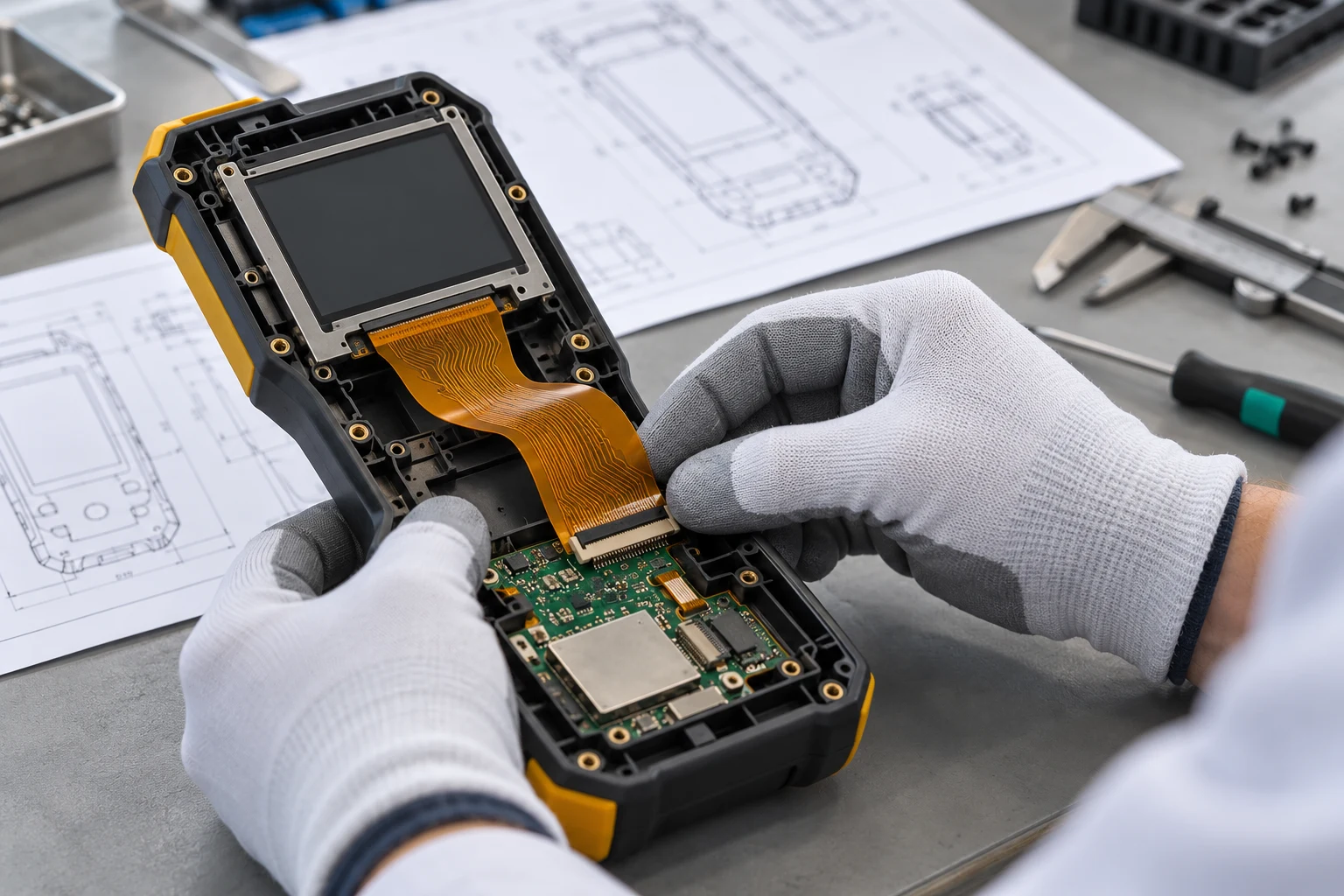

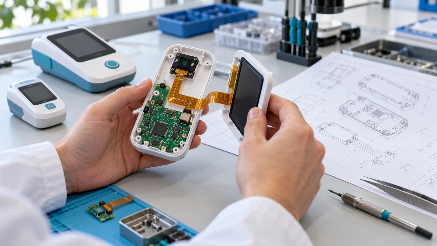
Medical device FPC: start with the installed assembly
A medical device FPC is a flexible printed circuit used to connect or support electronics within a medical device. For an OEM, its useful specification combines the electrical interface, installed shape, connector support, operating environment and acceptance checks. Selecting a thin circuit without defining those conditions leaves important integration questions unanswered.
Consider a portable diagnostic reader with a sensor board in its nose and a display in the lid. The interconnect may fit perfectly when the enclosure is open, yet become trapped against a screw boss when the lid closes. It may also carry a small sensor signal beside display switching currents. These are assembly-level decisions that a flat fabrication drawing cannot settle alone.
This guide addresses internal interconnect planning for non-implantable diagnostic, monitoring and imaging equipment. It provides an engineering review sequence, not a released medical design. Use the medical device FPC solutions page to discuss the application, then develop the drawing and verification package described below.
Define the device boundary before selecting a circuit
Start by identifying exactly where the FPC sits and what it does. An internal display link, a sensor connection and a moving probe interconnect can require different constructions even when they belong to the same product. Record the installation boundary before asking a supplier to recommend materials.
- Function: sensor readout, digital data, display, power distribution or a combination.
- Location: enclosed housing, removable module or exposed interface.
- Handling: factory installation, servicing, repeated articulation or routine replacement.
- Exposure: local heat, moisture, cleaning processes and possible fluid paths.
- Ownership: who approves the mechanical drawing, electrical limits and device qualification plan.
Record foreseeable assembly and service conditions as well as normal operation. For example, opening a cover may briefly extend a flex beyond its normal installed route. If the service procedure allows that movement, the design review should include it. If it does not, define the restraint and instructions that keep the part within its approved route.
Map each signal and its return path
Group the circuits by electrical behavior before arranging them on the flex. A medical sensor flexible PCB may carry low-level analog signals alongside clocks, display data and power. A shared connector does not mean those signals should share an uncontrolled return path or identical routing assumptions.
Prepare an interface table covering source and destination, pin assignment, voltage range, expected current, signal bandwidth or edge rate, reference conductor and any impedance requirement. Identify the sensitive input at the receiver, rather than labeling every trace simply as a signal. Include startup, charging and display activity in the operating scenarios.
Analog Devices' ADC layout guidance illustrates why return-current paths and coupling to sensitive circuitry deserve deliberate attention. Apply the recommendations for your actual sensor and converter; there is no universal grounding layout for all medical electronics.
For interfaces that need transmission-line control, coordinate the target, stack-up and measurement method using the controlled impedance flex PCB planning guide. Do not assign an impedance value merely because a product is described as high frequency.
Review routing with the housing closed
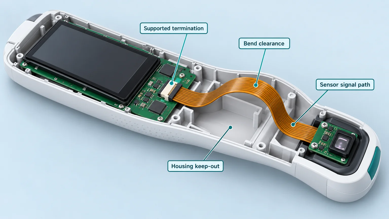
Check the flex route in its final three-dimensional position, including the path used during assembly. A useful drawing shows mounting points, bend direction, connector orientation and nearby keep-out features. The objective is to make the intended route repeatable for the person assembling the device.
Examine the clearance around screw bosses, sharp housing edges, battery pockets and heat-generating parts. Confirm that closing the enclosure does not flatten a service loop or pull the flex against its connector. Include part tolerances and the possible positions of adjacent wires or foam pads; the nominal CAD position is only one condition.
For a diagnostic reader, a practical review uses an enclosure sample, the intended connector and a representative flex construction. Photograph the open and closed routing positions and identify any assembly steps that require support. Resolve interference before treating the outline as released. General routing principles are covered in the flexible PCB design guidelines.
Separate installation bends from repeated movement
State whether each bend occurs during installation, occasional servicing or repeated operation. That distinction affects the questions asked about copper, layer structure, bend geometry and validation. A flex circuit that can be formed into a compact enclosure is not automatically suitable for continuous motion.
Mark bend regions on the mechanical drawing and show the direction of movement. Avoid placing a component, stiffener edge, abrupt width change or via transition in an active bend without a specific design review. Keep the intended flexing section distinct from the supported termination so movement does not concentrate at the connector.
For recurring motion, provide the actual range, speed, environment and required operating history. Agree on a representative test arrangement and acceptance criteria before selecting a construction. Neither a generic bend-radius ratio nor a supplier's unrelated cycle result proves suitability for your assembly.
The static and dynamic bend-radius guide explains the inputs needed for that discussion. Confirm the resulting geometry in the installed device, including any motion caused by servicing or handling.
Specify the complete stack-up and local reinforcement
Define the copper, dielectric, adhesives, coverlay and stiffeners together. “Polyimide FPC” is not a complete material specification: two circuits with the same base-film name can differ in finished thickness, reinforcement and assembly behavior. Record the proposed construction and the regions where it changes.
For example, DuPont's Pyralux LF laminate data sheet describes an adhesive-based construction with different copper and film options. It illustrates why a material family must be narrowed to an actual construction. It does not establish that a particular finished circuit meets your device requirements.
Use the flexible PCB materials guide to organize the stack-up review. Identify the required material records, allowed substitutions and approval process. If the project needs a particular supplier qualification or certification, confirm its current scope and evidence before placing the order; do not infer it from an application name.
Review any reinforcement as a local mechanical feature. Its outline, adhesive and position should be controlled alongside the flex layers.
Control connector fit and strain relief
Select the connector and its flex termination as a matched interface. Specify the exact connector drawing, contact side, conductor pitch, exposed-contact geometry and finished insertion thickness. Include the stiffener and adhesive in the relevant thickness calculation instead of quoting only the bare flex thickness.
Check access for the latch and the insertion tool or operator's fingers. A connector that can be reached on an open PCB may become inaccessible after the display or battery is installed. Record the assembly order and provide support so insertion force does not bend a populated area or load the flex route.
Hirose's connector documentation provides series-specific drawings and handling guidance. Use the chosen connector's current documents rather than transferring a thickness or routing rule from a different series.
Compare the supported end with the nearby bend region using the flexible PCB stiffener guide. Verify both retention and service access in the prototype, including the planned number of connector mating operations.
Define cleaning exposure and patient-contact boundaries
Describe what reaches the FPC, rather than applying a general label such as “medical grade.” An enclosed internal circuit may experience different conditions from an exposed probe assembly. Record the actual cleaning process, possible ingress routes, temperatures and repeated exposures relevant to the installed construction.
If disinfection or sterilization is part of the device process, define the process and the finished assembly that will be evaluated. Review adhesives, coatings, connectors and residues together. A base material's temperature rating alone cannot establish compatibility with that process.
The FDA's biocompatibility overview distinguishes body-contact considerations and evaluates the device in its finished form, including sterilization when applicable. An internal-part label is not a conclusion about the complete device. The OEM should define the contact assessment and supporting evidence for its intended use.
Keep those requirements separate from ordinary circuit fabrication acceptance. A continuity report provides electrical evidence for the circuit; it does not establish biocompatibility or authorize a medical application.
Plan assembly support and inspection access
Review how the FPC will be supported, populated, inspected and installed. Flexible material needs a controlled assembly route so handling and joining operations do not introduce damage before the part reaches the enclosure. The required support depends on the actual construction and component locations.
For an assembled flex, provide the BOM, component orientation, placement data, soldering requirements and areas that must remain free of fixtures or adhesive. Identify accessible inspection points and discuss what cannot be seen after the housing closes. Agree on any rework restrictions and the records needed to track an approved repair.
Include the flex installation in the assembly review: who holds the display, when the connector is latched, how the loop is formed and where the final routing is checked. A clear sequence can reveal a need to change the outline or reinforcement before production tooling is committed.
The FPC assembly guide provides a broader framework for discussing carriers, assembly information and acceptance checks with the manufacturing team.
Build a verification matrix before ordering prototypes
Turn each important design requirement into an observable check with an owner and an acceptance rule. The following matrix is a planning example, not a mandatory medical test standard. Select methods and limits for your device, its risks and its intended operating conditions.
| Requirement | Representative check | Evidence to retain |
|---|---|---|
| Correct circuit connections | Agreed continuity and isolation checks | Revision, test method and circuit result |
| Repeatable enclosure fit | Install in representative housing positions | Fit observations and routing photographs |
| Stable sensor or display interface | Operate relevant device modes with the installed flex | Setup, operating conditions and measured result |
| Supported connector termination | Inspect insertion, retention and strain relief | Connector revision and assembly findings |
| Appropriate environmental behavior | Application-specific exposure and follow-up checks | Process, samples and agreed pass criteria |
Keep circuit tests, subassembly tests and complete-device evaluation identifiable. If one activity is excluded from the supplier's quotation, assign it elsewhere explicitly. Unassigned validation work should not disappear between purchasing and engineering.
Test representative prototypes in the intended configuration
Use prototypes to investigate the assumptions that cannot be resolved from drawings alone. A flat circuit on a bench can answer some electrical questions, but it cannot demonstrate the final route, connector access or interaction with the closed housing. Include the intended mechanical configuration in the test plan.
For the diagnostic-reader example, compare sensor operation with the display idle and active, inspect the flex after installation, and review the service-opening sequence. These are suggested investigation points; the OEM must choose appropriate test conditions, limits and instrumentation for the actual device.
Record which materials, connector parts, firmware and enclosure revision were used. A positive result is only meaningful within that documented configuration. When an early prototype uses a temporary housing or substitute component, identify which findings remain provisional.
The flexible PCB prototype validation guide helps structure those records. Resolve the findings before releasing a production package, and preserve the reason for each accepted deviation.
Set traceability and change-control expectations
Agree on the evidence that must travel with each build and the changes that require review. A useful traceability plan connects the delivered circuit to the approved design revision, material information, manufacturing lot and agreed inspection records. Its depth should follow the project's documented requirements.
Discuss substitutions before they occur. A replacement adhesive, surface finish, connector or coverlay construction may need a different review from an administrative drawing correction. Specify who evaluates the effect, what evidence is required and how approval is recorded.
Keep the purchasing description aligned with engineering documentation. Avoid ordering by a photograph, an informal sample name or a headline thickness after the design has changed. Include a release identifier that both the OEM and supplier can recognize.
Finally, define how nonconforming parts and approved deviations are handled. The quotation should make the expected documentation and responsibilities visible; it should not imply that every possible inspection or device qualification activity is included automatically.
Prepare a medical device FPC RFQ that can be reviewed
Send one revision-controlled package that connects the application to the manufacturing data. A supplier can review a medical flexible PCB more effectively when the intended route, connector interface and acceptance requirements are clear. Identify unresolved decisions rather than disguising them as final specifications.
- Application description, installation drawing and relevant exposure conditions.
- Gerber or agreed CAD data, drill information, outline and proposed stack-up.
- Connector drawings, reinforcement details and critical finished dimensions.
- Electrical requirements, bend conditions and prototype acceptance plan.
- BOM and placement data when assembly is requested.
- Quantities, delivery stages and required supplier or material documentation.
Ask the supplier to distinguish confirmed requirements, proposed alternatives and exclusions. If a tolerance or material remains undecided, record it as an open item with an owner. Use the flexible PCB RFQ checklist to keep those decisions in one package before comparing quotations.
Review application options without assuming qualification
Use application examples to identify an appropriate technical discussion, then verify the details for your own device. A monitoring interface, an ultrasound probe and a compact optical scanner have different channel, geometry and assembly priorities. Their names alone do not establish interchangeable constructions.
The medical device FPC product category groups relevant starting points. When reviewing a listed example, ask which features apply to the proposed project, what can be changed and what evidence is available. The related products below are discussion references, not statements that your finished device has been qualified.
Coordinate adjacent functions as well. A diagnostic instrument may need both display FPC integration and a wireless interface. The medical, display and communication solutions below can help organize those conversations without treating a shared technology as a universal medical specification.
Keep prototype evidence, supplier qualification and device-level responsibilities distinct through the final design review.
Related Medical FPC Products
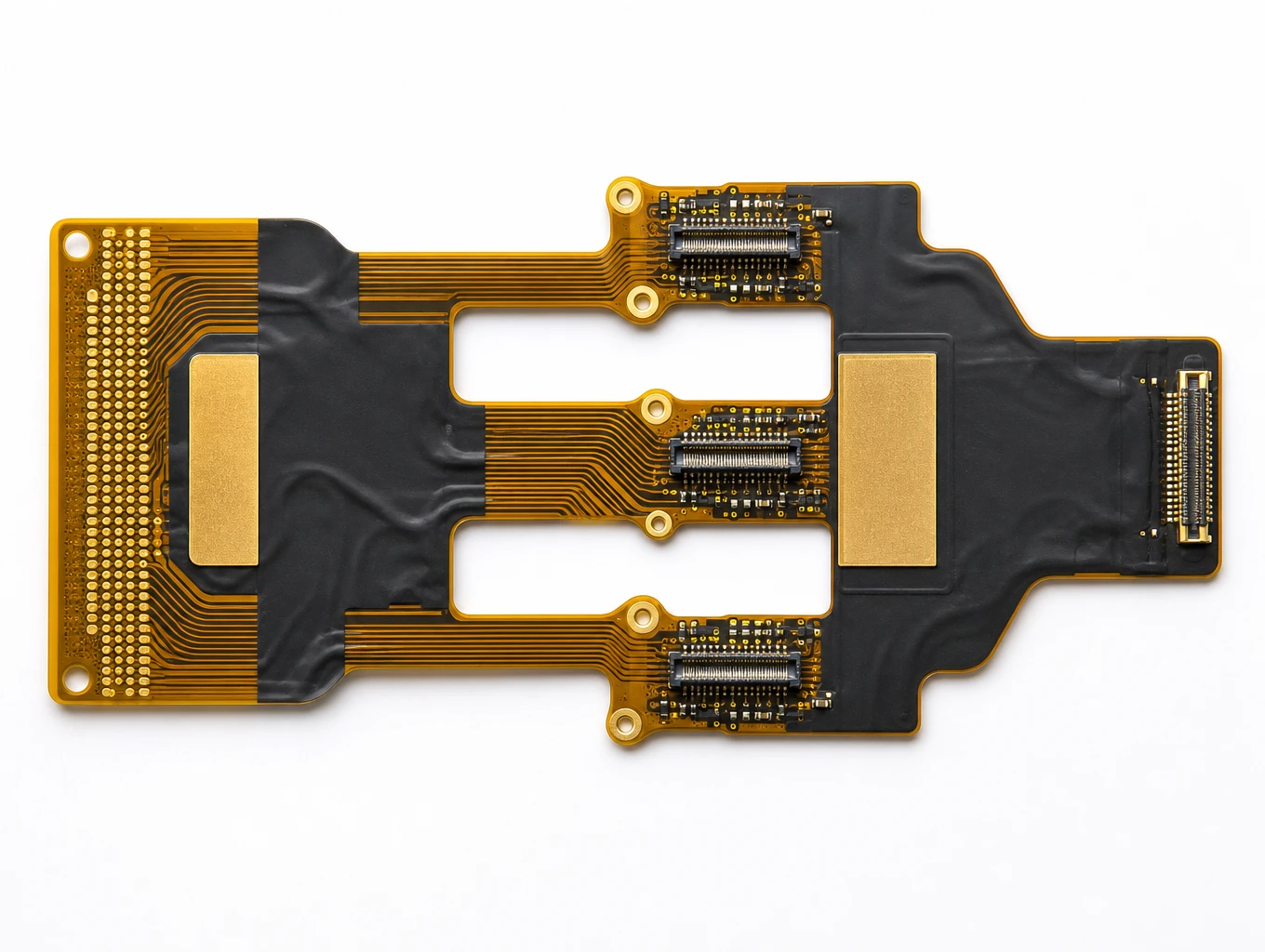
High-Frequency Ultrasound Transducer Probe Multi-Layer FPC
Model: TLX-MED-USND02
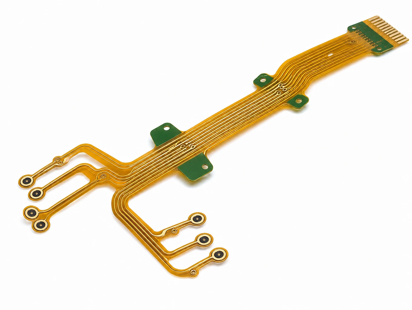
Multi-Lead ECG / EEG Diagnostic Patient Monitor Flex Ribbon
Model: TLX-MED-DIAG05
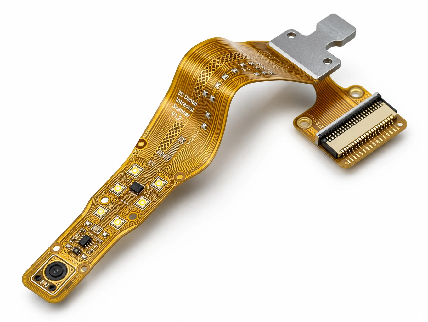
Dental Intraoral 3D Optical Scanner & Imaging Wand FPC
Model: TLX-MED-DENT06
Related FPC Solutions
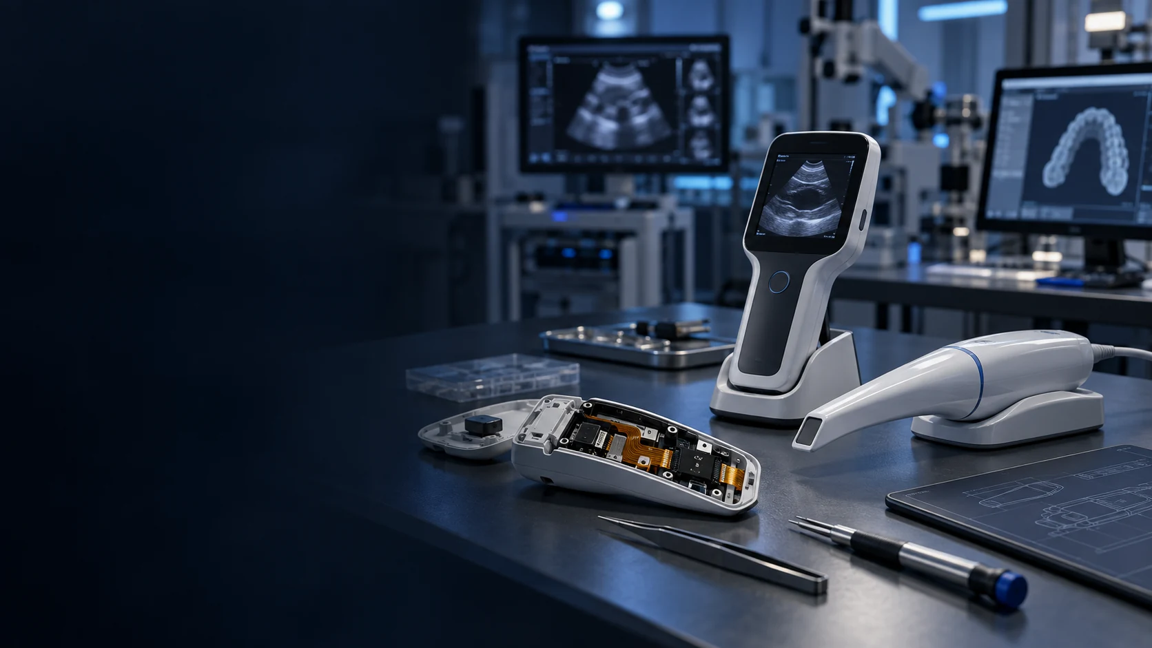
Medical Device FPC Solutions
Custom flexible circuits for diagnostic equipment, patient monitoring and compact medical electronics. Discuss routing, signal paths, materials and prototype acceptance with Teleconix before releasing your OEM design.
Explore Solutions
Display FPC
Display FPC products for OLED, AMOLED, micro-LED and TFT-LCD modules in handheld, wearable, automotive and industrial devices. Review the display interface, connector and installed flex shape together.
Explore Solutions
RF & Communication FPC Solutions
Custom RF flexible PCB and telecom interconnects for antenna modules, wireless terminals and high-speed communication assemblies. Coordinate materials, signal paths, shielding and connector support with Teleconix before prototype release.
Explore Solutions Medical Device FPC Solutions
Custom flexible circuits for diagnostic equipment, patient monitoring and compact medical electronics. Discuss routing, signal paths, materials and prototype acceptance with Teleconix before releasing your OEM design.
Explore Solutions Display FPC
Display FPC products for OLED, AMOLED, micro-LED and TFT-LCD modules in handheld, wearable, automotive and industrial devices. Review the display interface, connector and installed flex shape together.
Explore Solutions RF & Communication FPC Solutions
Custom RF flexible PCB and telecom interconnects for antenna modules, wireless terminals and high-speed communication assemblies. Coordinate materials, signal paths, shielding and connector support with Teleconix before prototype release.
Explore SolutionsMedical Device FPC FAQs
Conclusion: release a defined interconnect, not just a drawing
A useful medical device FPC specification describes the complete installed interconnect: signal paths, mechanical routing, connector support, material exposure and the evidence needed for acceptance. Agree on those points before treating the prototype as a production reference.
Prepare your drawings, application conditions and open questions, then discuss the medical FPC project with Teleconix. The next step is a review of the proposed construction, required documentation and prototype scope so both teams work from the same release package.